


xE922-3GR Hardware User Guide
1VV0301272
Rev.0.8 2017-01-05
Reproduction forbidden without written authorization from Telit Communications S.p.A. - All Rights
Reserved.
Page 72 of 112
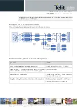
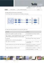
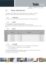
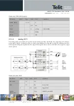
12.2.
USIF
xE922-3GR offers two
‘
Universal Serial Interface
’ ports
, configurable either as SPI or UART
·
USIF1 :SPI (up to 48MHz) / UART
·
USIF2 :SPI (up to 26MHz) / UART
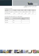
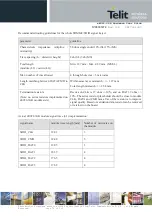
PAD
Signal
I/O
descriptions
Type
USIF 1 (UART/SPI)
W5
USIF1_RXD
I
UART1 / SPI1 Serial data input
CMOS 1.8V
Y5
USIF1_TXD
O
UART1 / SPI1 Serial data Output
CMOS 1.8V
S5
USIF1_SCLK
I/O
UART1 RTS / SPI1 SCLK
CMOS 1.8V
U5
USIF1_CS
O
UART1 CTS / SPI1 Chip Select
CMOS 1.8V
USIF 2 (UART/SPI)
AH3
USIF2_RXD
I
UART2 / SPI2 Serial data input
CMOS 1.8V
AE4
USIF2_TXD
O
UART2 / SPI2 Serial data Output
CMOS 1.8V
AD5
USIF2_SCLK
I/O
UART2 CTS / SPI2 SCLK
CMOS 1.8V
AJ2
USIF2_CS
O
UART2 RTS / SPI2 Chip Select
CMOS 1.8V
Remark:
USIF1 pinning is also multiplexed with an optional digital audio I2S interface bus (refer to audio chapter).
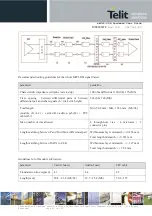
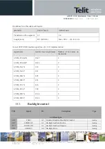
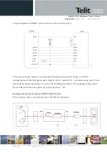
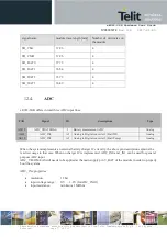
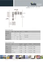
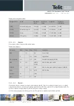
Routing guide lines for the USIF interface (SPI mode):
Recommended routing guidelines for the whole USIF signal traject:
parameter
guideline
Characteristic impedance (stripline / microstrip)
50 ohm single ended 10%(SL) 15%(MS)
Trace spacing : between differential pairs or between
differential pair and other signals (h = dielectric height)
2xh (SL) 3xh (MS)
Total length (module (L1) + carrier(L2))
Min. 5.1 mm / Max. 330.2 mm (MS/SL)
Max. number of vias allowed
4 through-hole vias + 4 microvias
Length matching between DATA to CLK
Total length mismatch: +/- 12.7 mm