ADR-7000 / SAVER-7000 / GUARD-7
© 2017
– Telefire Fire & Gas Detectors Ltd
Revision 0.98 October 2017
– Page 25 of 87 –
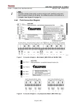
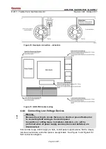
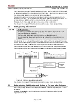
Figure 9 Connection diagram
– GUARD-7
4.4.3 Testing the SLC Loops
Resistance measurements:
Short the end of one branch and measure the resistance from the connections of the
loop to the control panel. Make su
re that the resistance does not exceed 40Ω. Repeat
for each input or SLC. For systems that have an NFPA SLC style 4 T branching repeat
the test for each branch separately. Make sure that the sum of all branches in a loop
does not exceed 40Ω.
Figure 10 Testing Loop Resistance
Capacitance measurements:
Connect all branches and ensure that the total capacitance of a loop does not exceed
1.0µF
Figure 11 Testing Loop Capacitance

