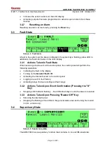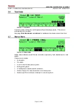
ADR-7000 / SAVER-7000 / GUARD-7
© 2017
– Telefire Fire & Gas Detectors Ltd
Revision 0.98 October 2017
– Page 15 of 87 –
4
Installation
The planning process should take into consideration the entire system.
Start by going over the project plans and determine the quantity and location of various
detectors, call points, sounders, strobes, and other fire-safety devices as required.
Consider the NFPA 72 recommendation, local guidelines and regulations, and specific
requirements set by the fire safety consultant.
Make a list of the equipment required, taking into consideration and additional items
necessary as pre-requisite or optional accessories.
Calculate the number of addresses needed and make sure that there are sufficient
quantities of control panels and loops per control panels and allow for some spare
addresses for future requirements.
Calculate cable lengths
– long cable runs may require additional control panels, loops or
auxiliary power supplies.
Calculate the current-draw requirements, both for a quiescent system and in alarm.
Calculate the size of batteries required and additional auxiliary power supplies that may
be needed.
Specify logical zones and activation matrices so that the installing engineer can
configure the control panels as necessary.
NFPA 72
NFPA 72 Recommendation
The NFPA (National Fire Protection Association) is the American association
for the fire safety industry. Its guideline, NFPA 72 National Fire Alarm and
Signaling Code specifies "the application, installation, location, performance,
inspection, testing, and maintenance of fire alarm systems, fire warning
equipment and emergency warning equipment, and their components" and is
considered the de-facto standard of fire alarm design and implementation.
4.1
Pre-Installation Planning
Planning of quantity and location of detectors, push buttons, notification appliances and
extinguishing devices shall be done according to the local codes and regulations and in
accordance to the planning consultant's requirements.
4.1.1 Pre-Installation Planning
– Capacity Planning
Calculate the number of addresses required by the system's devices.
Round up by 10% to provide sufficient available addresses to allow for future expansion
and divide by 127. Round up to the nearest whole number to calculate the required
number of SLC loops.
Divide the number of loops by 4 and round up to the nearest whole number to calculate
the minimum number of control panels required.
In some cases site-specific requirements may determine the need for more loops and/or
control panels than the minimum.
If you need more than one control panel, you will need to network multiple panels.
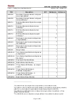
P/N
Description
QTY
Multiply by
Addresses
TFO-480A
Photo-Electric Smoke Detector
1
TFH-280A
Heat Detector
1
TPH-482A
Photo/Heat Detector
1

