ADR-7000 / SAVER-7000 / GUARD-7
© 2017
– Telefire Fire & Gas Detectors Ltd
Revision 0.98 October 2017
– Page 51 of 87 –
9. 3V Battery: battery voltage (this battery is used for configuration back up when the
control panel is powered off)
10. Total current: total current from all 24Vdc outputs; both NACs and all loops
11. Temperature: main board temperature
12. RM Control:
13. RM Control:
14. RM Control:
15. LON Net Diagnostic: LON communication diagnostics (communication between
control panels in a network)
16. I2C Diagnostics: I2C communication diagnostics (this is the internal communication
between in the control panel)
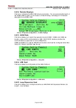
8.5.9 Device Address Programming
Allows address programming to a detector that is connected to J28 on the main board.
Manual
– set an address to each detector
Automatic
– increases the address by 1 after each address setting.
8.6
Walk Test
This feature allows the testing of all the initiating devices of the system.
The device test is performed by placing a
magnet near the detector’s test point or by
activating the alarm call-points with the test key (supplied with the call-points).
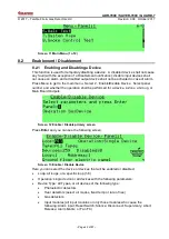
Entering the Walk Test mode is done through the main menu and requires a password.
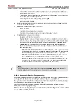
From the main menu select
6 Walk Test
. The following message is displayed:
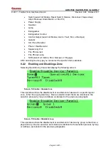
Key in 1 to select devices for testing. The next menu shall allow the selection of loops;
zones; or groups for testing. Press Enable to add the devices to be tested. Press Exit
and save changes.
The
Walk Test
LED shall turn on to indicate that a walk test is currently done.
Start testing by initiating the devices. Upon activation of the device, the device alarm
indicating LED will light and the device address will be displayed on the LCD. After 15
seconds the system will perform automatic reset to the device. During the automatic test
no outputs are activated.
An alarm received from a device that is not in Walk Test mode will abort the Walk Test
will activate the alarm.
Two simultaneously alarms from the tested card will abort the Walk Test procedure and
activate the alarm.
A device that is programmed as delayed will respond to the test immediately.
To stop the automatic test process, press the
Quit
key.
When you complete the testing go to the Walk Test menu and define the devices as
normal operation again.
The system aborts the walk test and returns to normal operation if no devices are tested
for 15 minutes.
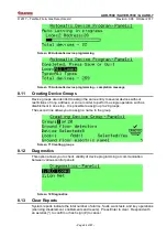
8.6.1 Select Devices
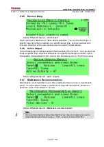
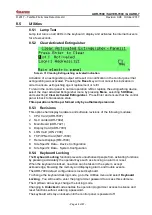
Select the loops for testing. Press Enable while selecting the Test field to change field
value from Test Disabled to Test Enabled.

