ADR-7000 / SAVER-7000 / GUARD-7
© 2017
– Telefire Fire & Gas Detectors Ltd
Revision 0.98 October 2017
– Page 67 of 87 –
9
Troubleshooting
9.1
LEDs
9.1.1 LEDs on the User Display
See section 6.2 on page 34 for an explanation of LEDs.
9.1.2 LEDs on the Main Board
The red LED light next to the battery connector on the main card turns on when the
charger charges the batteries.
The addressable device
communication circuit line (SLC) is electronically protected
against short circuits. The circuit will break the loop if there is a short circuit and it will
return to normal operations automatically upon removal of the short circuit. Each circuit
line includes two LED indicator lights that allow maintenance to distinguish between the
following situations:
Flashing red light (LED 3) indicates that it is addressing an addressable device
Solid yellow light (LED 4) indicates a communication fault, including in the event of a
momentary fault that does not activate a system wide fault mode
9.1.3 LEDs on the Loop Card
The LEDs at the line cards have electronic protection form shorts. The circuitry shall
disconnect the loop if it senses a short and will resume normal operation when the fault
is rectified. Every line card has two LEDs to indicate the following conditions:
A red LED (LED 1) flickers upon every communication with addressable device.
A yellow LED (LED 2) is on whenever there is a communication error, even for a
temporary error
9.2
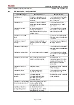
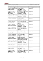
Control Panel Error Messages
i
Note
The pound sign (#) in the messages listed in the table of error notices
represents a number that indicates the panel's number, loop card number, or
device address.
9.3
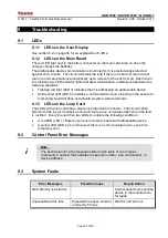
System Faults
Error Messages
Possible Cause
Repair Action
Main Memory is defective
Control panel fault- send the
device to the manufacturer
for repair
Unavailable at this time
Password has been entered
incorrectly 5 times
Wait for half an hour


