29
FLYWHEEL (INSIDE-EDGE) BRAKE SYSTEM
Tecumsehs brake systems provide two methods of
meeting compliance standards which has become a
Federal law as of June 30, 1982. There are two additional
methods used by equipment manufacturers that also
meet compliance standards, they are:
1. Use of the blade brake clutch in conjunction with
either a top or side mounted recoil starter. The blade
stops within three seconds after the operator lets
go of the blade control bail at the operator position
and the engine continues to run. Starter rope handle
is on the engine.
2. Use of a recoil starter (top or side mounted) with
the rope handle on the engine as opposed to within
24 inches from the operator position. This method
is acceptable if the mower deck passes the 360
degree foot probe test. A specified foot probe must
not contact the blade when applied completely around
the entire blade housing. This alternative can be
used with engine mounted brake systems and typical
bail controls. The blade stops within three seconds
after the operator lets go of the blade control bail
at the operator position and the engine is stopped.
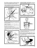
Tecumsehs Flywheel (Inside-Edge) Brake System
provides consumer safety by shutting down the engine
and lawnmower blade within seconds after the operator
releases the Engine/Blade control at the handle of the
lawnmower.
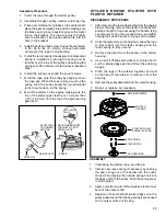
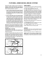
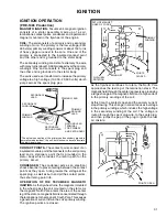
INSIDE EDGE SYSTEM
In the stop position the brake pad is applied to the
inside edge of the flywheel, at the same time the ignition
system is grounded.
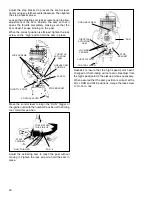
In order to restart the engine, the brake control must
be applied. This action pulls the brake pad away from
the inside edge of the flywheel and opens the ignition
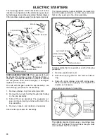
kill switch. On electric start systems the starter is
energized by an ignition switch or a two motion control.
On non-electric start systems, the recoil starter rope
must be pulled to start engine.
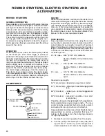
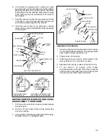
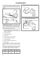
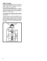
COMPONENTS
The Inside Edge system uses the following components:
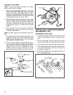
The
brake lever and pad
assembly consists of a steel
lever with a brake pad bonded to the lever.
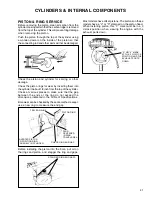
The
ignition kill switch
is a plastic block with a wire
extending out of it. The wire is attached to a terminal
which is connected to the ignition kill wire. The brake
lever contacts and grounds the wire of the switch when
the engine / blade control is released, and the ignition
module is grounded. This in turn kills the ignition.
The
interlock switch
is a push button switch that is
activated by the brake lever when the engine / blade
control is actuated. If there is a starter switch used
to start the engine, the interlock switch acts as a safety
switch and will not allow the starter to crank unless
the engine / blade control is depressed.
Where a two motion control is used the interlock switch
is utilized as the starter switch.
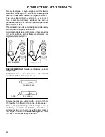
The
Torsion Spring
supplies the pressure to the brake
lever and brake pad to stop the flywheel.
The
Control Cable
transfers the motion of the
engine / blade control to the brake system.
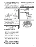
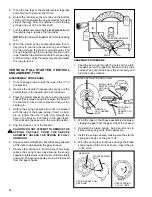
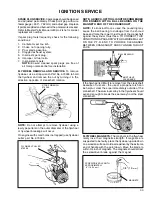
SERVICE
If the brake system fails to kill the ignition and stop
the blade within 3 seconds the following service procedures
should be followed.
Remove the flywheel as outlined in "IGNITION" section.
NOTE:
BEFORE THE FLYWHEEL IS REMOVED OR
REPLACED, THE BRAKE PRESSURE ON THE
FLYWHEEL MUST BE RE-LEVELED AS OUTLINED.
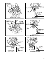
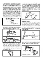
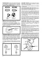
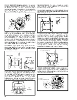
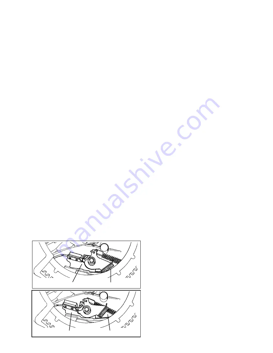
BRAKE APPLIED
IGNITION SHORTED
BRAKE RELEASED
IGNITION OPEN
Содержание AH520 -
Страница 67: ...64...


