


7
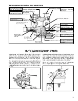
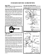
OPERATION
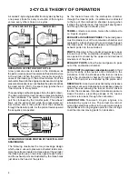
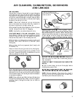
In the CHOKE or START position, the choke shutter
is closed, and the only air entering the engine enters
through openings around the shutter. As the engine
starts to rotate the downward piston travel will create
a low air pressure area in the engine cylinder above
the piston. Higher pressure (atmospheric air) rushes
into the engine to fill the created low pressure area.
Since the majority of the air passage is blocked by
the choke shutter, a relatively small quantity of air
enters the carburetor at increased speed. The main
nozzle and both idle fuel discharge ports are supplying
fuel due to the low air pressure in the intake of the
engine. A maximum fuel flow through the carburetor
orifices combined with the reduced quantity of air that
passes through the carburetor, make a very rich fuel
mixture which is needed to start a cold engine.
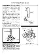
At engine IDLE speed, a relatively small amount of
fuel is required to operate the engine. The throttle is
almost completely closed. A fuel / air mixture is supplied
through the primary idle-fuel discharge orifice during
idle.
During INTERMEDIATE engine operation, a second
orifice is uncovered as the throttle shutter opens, and
more fuel mixture is allowed to atomize with the air
flowing into the engine.
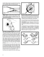
During HIGH SPEED engine operation, the throttle
shutter is opened. Air flows through the carburetor
at high speed. The venturi, which decreases the size
of the air passage through the carburetor, further
accelerates the air flow. This high speed movement
of the air decreases the air pressure at the main nozzle
opening. Fuel is forced out the main nozzle opening
due the difference in the atmospheric air pressure
on the fuel in the carburetor bowl and the reduced
air pressure at the main nozzle opening.
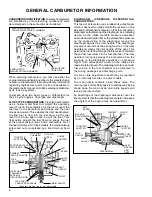
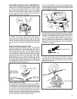
CARBURETOR SERVICE.
Carefully disassemble
carburetor, removing all non-metallic parts, i.e., gaskets,
viton seats and needles, O rings, fuel pump valves,
etc.
Nylon check balls used in some diaphragm carburetors
are not serviceable. Nylon can be damaged if subjected
to harsh cleaners for prolonged periods.
Remove the primer bulb (if equipped) by grasping with
a pliers and pulling and twisting out of the body. Remove
the retainer by prying and lifting out with a screwdriver.
Do not re-use old bulb or retainer.
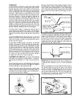
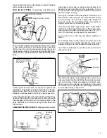
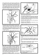
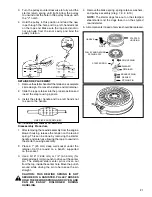
Remove all welch plugs if cleaning the carburetor. Secure
the carburetor in a vise equipped with protective jaws.
Use a small chisel sharpened to a 1/8" wide wedge
point. Drive the chisel into the plug to pierce the metal
and push down on the chisel to pry the plug out of the
hole.
Clean all metallic parts with solvent.
ABOUT 1/8" WIDE
WELCH PLUG
TO BE REMOVED
PRY OUT
PLUG
PIERCE PLUG WITH TIP
SMALL
CHISEL
DO NOT ALLOW CHISEL
POINT TO STRIKE
CARBURETOR BODY
OR CHANNEL REDUCER
SMALL CHISEL
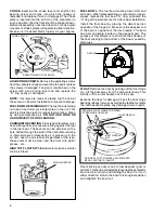
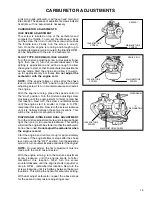
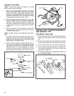
NEW WELCH PLUG
SAME OR LARGER
DIAMETER OF PLUG
FLAT-END PUNCH
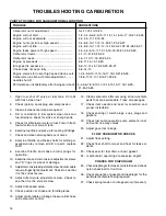
THROTTLE PLATE
THROTTLE LEVER
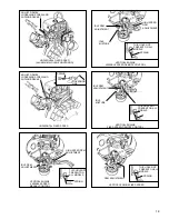
To install a new welch plug after cleaning, place welch
plug into receptacle with raised portion up. With a
punch equal to the size of the plug, merely flatten
the plug. Do not dent or drive the center plug below
the top surface of the carburetor. After installing the
welch plug, seal the outer diameter with finger nail
polish. (Do not use clear polish).
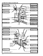
THROTTLE.
Examine the throttle lever and plate prior
to disassembly. Replace any worn and/or damaged
parts.
When reassembling, it is important that the lines on
the throttle plate are facing out when in the closed
position. Position throttle plates with the two lines at
12 and 3 oclock. If throttle plate has only one line,
the line should be positioned in the 12 oclock position.
If binding occurs, correct by loosening the screws
and repositioning the throttle plate.
Содержание AH520 -
Страница 67: ...64...


