3-71
•
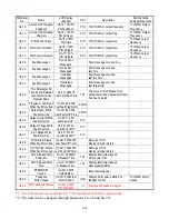
3 different commands are used for communication between the inverter and
external units:
a.
Read command: external units to read the memory address of the inverter.
b.
Write command: external units to write the memory address of the inverter in
order to control the inverter.
c.
Circuit test command: To test the communication status between the inverter
and external units.
•
The change of setting Sn-36, Sn-37, Sn-38 will be effective in the next start time
after turning off the inverter.
•
Do not make the DRIVE/PRGM changeover while writing the date into the inverter
through RS-485 port.
•
For more details of RS-485 communication, refer to
“RS-485 MODBUS/PROFIBUS Communication Application Manual”.
(40)
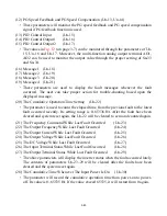
PG Speed Control Settings
(Sn-40)
Sn-40 = 0 : Disable speed control function.
= 1 : Enable speed control.
= 2 : Enable speed control. No integral action during ACC/DEC.
= 3 : Enable speed control. Integral action is enabled.
(41)
Operation Selection at PG Opens
(Sn-41)
Sn-41 = 0 : deceleration to stop (Bn-02)
= 1 : coast to stop
= 2 : deceleration to stop (Bn-04)
= 3 : continue to run
}
Display “PG Open” alarm.
Blinking display “PG Open” alarm.
(42)
Operation Selection at PG Speed Deviation Over (Sn-42)
Sn-42 = 0 : deceleration to stop (Bn-02)
= 1 : coast to stop
= 2 : deceleration to stop (Bn-04)
= 3 : continue to run
}
Display “Sp.
Deviate
Over” fault
message.
Blinking display “Sp.
Deviate
Over”
alarm
(43)
Overspeed Detection (Sn-43)
Sn-43 = 0 : deceleration to stop (Bn-02)
= 1 : coast to stop
= 2 : deceleration to stop (Bn-04)
= 3 : continue to run
}
Display “Over Speed” fault message.
Blinking display “Over Speed” alarm.
Содержание MA7200
Страница 26: ...1 22 ...
Страница 153: ...DISTRIBUTED BY 5100 NORTH IH 35 ROUND ROCK TEXAS 78681 www tecowestinghouse com 03 14 2005 ...


