


Technosoft 2016
32
iPOS4808 MY-CAN-STO/-CAT-STO Technical Reference
3.6.8
Power Supply and STO Connection
3.6.8.1
Supply Connection
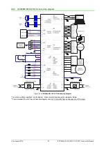
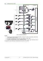
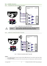
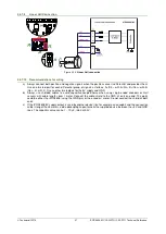
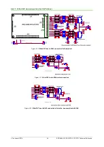
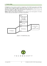
Figure 3.26.
Supply connection
* The STO and +Vlog inputs can be supplied from the same power source as long as its output voltage is 18 to 36V DC
from a SELV/ PELV power supply.
3.6.8.2
Recommendations for Supply Wiring
Always provide a nearby capacitor on the motor supply lines. The capacitor should be located within 10cm of the
iPOS4808 connector, max. 20cm. The minimum recommended capacitance is 330µF for iPOS4808, always rated at
the appropriate voltage.
Use short, thick wires between the iPOS4808 and the motor power supply. Connect power supply wires to all the
indicated pins. If the wires are longer than 2 meters, use twisted wires for the supply and ground return. For wires longer
than 20 meters, add a capacitor of at least 2,200μF (ra
ted at an appropriate voltage) right on the terminals of the
iPOS4808.
3.6.8.3
Recommendations to limit over-voltage during braking
During abrupt motion brakes or reversals the regenerative energy is injected into the motor power supply. This may
cause an increase of the motor supply voltage (depending on the power supply characteristics). If the voltage bypasses
53V, the drive over-voltage protection is triggered and the drive power stage is disabled. In order to avoid this situation
you have 2 options:
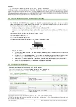
Option 1. Add a capacitor on the motor supply
big enough to absorb the overall energy flowing back to the supply.
The capacitor must be rated to a voltage equal or bigger than the maximum expected over-voltage and can be sized
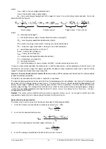
with the formula:
2
2
2
NOM
MAX
M
U
U
E
C
−
×
≥


