background image


 Technosoft 2016 

14 

iPOS4808 MY-CAN-STO/-CAT-STO Technical Reference


3.2  iPOS4808 MY-CAT-STO Board Dimensions 


Figure 3.2.1. 

iPOS4808 MY-CAT-STO drive dimensions 

All dimensions are in mm. The drawings are not to scale. 


Содержание iPOS4808 MYCAN-STO

Страница 1: ...iPOS4808 MY CAN STO CAT STO Intelligent Servo Drive for Step DC Brushless DC and AC Motors Intelligent Servo Drives Technical Reference Technosoft 2016 P091 027 iPOS4808 MY STO UM 1116 ...

Страница 2: ...5 iPOS4808 MY I O Evaluation board 12 3 Hardware Installation 13 3 1 iPOS4808 MY CAN STO Board Dimensions 13 3 2 iPOS4808 MY CAT STO Board Dimensions 14 3 3 Mechanical Mounting 15 3 3 1 iPOS4808 MY CAN STO PCB Footprint 15 3 3 2 iPOS4808 MY CAT STO PCB Footprint 15 3 4 Motherboard PCB Design 16 3 5 Connectors and Pinouts 17 3 5 1 Pinouts for iPOS4808 MY CAN STO 17 3 5 2 Mating Connectors for CAN a...

Страница 3: ...imit over voltage during braking 32 3 6 9 Serial RS 232 connection 34 3 6 9 1 Serial RS 232 connection 34 3 6 9 2 Recommendation for wiring 34 3 6 10 CAN bus connection for CAN drives only 35 3 6 10 1 CAN connection 35 3 6 10 2 Recommendation for wiring 35 3 6 11 EtherCAT bus connection for CAT drives 36 3 6 12 Removal from Autorun Mode 37 3 7 CAN Operation Mode and Axis ID Selection for CAN drive...

Страница 4: ...e commissioning Step 3 Motion programming using one of the options A CANopen master1 or an EtherCAT master2 The drives built in motion controller executing a Technosoft Motion Language TML program developed using Technosoft EasyMotion Studio software A TML_LIB motion library for PCs Windows or Linux 3 A TML_LIB motion library for PLCs 3 A distributed control approach which combines the above optio...

Страница 5: ...EtherCAT and describes the associated object dictionary Motion Programming using EasyMotion Studio part no P091 034 ESM UM xxxx describes how to use the EasyMotion Studio to create motion programs using in Technosoft Motion Language TML EasyMotion Studio platform includes EasySetUp for the drive motor setup and a Motion Wizard for the motion programming The Motion Wizard provides a simple graphica...

Страница 6: ...tions listed hereunder This information is intended to protect you the drive and the accompanying equipment during the product operation Incorrect handling of the drive can lead to personal injury or material damage The following safety symbols are used in this manual WARNING SIGNALS A DANGER TO THE OPERATOR WHICH MIGHT CAUSE BODILY INJURY MAY INCLUDE INSTRUCTIONS TO PREVENT THIS SITUATION CAUTION...

Страница 7: ...ation and Restriction of Chemicals which came into force on 01 06 2007 RoHS Compliance Technosoft SA here with declares that this product is manufactured in compliance with the RoHS directive 2002 95 EC on the restriction of the use of certain hazardous substances in electrical and electronic equipment RoHS Technosoft SA hereby declares that this product conforms to the following European applicab...

Страница 8: ...ribute the intelligence between the master and the drives in complex multi axis applications reducing both the development time and the overall communication requirements For example instead of trying to command each movement of an axis you can program the drives using TML to execute complex motion tasks and inform the master when these tasks are done Thus for each axis control the master job may ...

Страница 9: ...rge from Technosoft web page 2 2 Product Features Fully digital servo drive suitable for the control of rotary or linear brushless DC brush and step motors Very compact design Sinusoidal FOC or trapezoidal Hall based control of brushless motors Open or closed loop control of 2 and 3 phase steppers STO 2 safe torque off inputs safety integrity level SIL3 Cat3 PLe acc to EN61800 5 1 2 EN61508 3 4 EN...

Страница 10: ...ry for data acquisition 16K 16 E2 ROM to store TML motion programs cam tables and other user data PWM switching frequency up to 100kHz Motor supply 12 50V Logic supply 9 36V STO supply 18 40V Output current 81 continuous 20A peak Operating ambient temperature 0 40 C over 40 C with derating Protections Short circuit between motor phases Short circuit from motor phases to ground Over voltage Under v...

Страница 11: ...loop configurations The motor speed control loop is closed on one feedback connected on the motor while the motor position control loop is closed on the other available feedback which is placed on the load There is usually a transmission between the load and the motor Motor type Feedback 1 Feedback 2 PMSM Incremental encoder single ended or differential Analogue Sin Cos encoder Linear Halls only o...

Страница 12: ... the iPOS4808 features Figure 2 5 1 iPOS4808 MY CAN STO mounted on the I O iPOS4808MY extension board Ordering information Part number Description P091 084 IO iPOS4808MY UM xxxx Evaluation board User Manual available for download on our website P027 414 E881 I O iPOS4808 MY extension board only P027 314 E803 iPOS4808 MY CAN STO Starter kit without motor P027 314 E804 iPOS4808 MY CAN STO Starter ki...

Страница 13: ...3 iPOS4808 MY CAN STO CAT STO Technical Reference 3 Hardware Installation 3 1 iPOS4808 MY CAN STO Board Dimensions Figure 3 1 1 iPOS4808 MY CAN STO drive dimensions All dimensions are in mm The drawings are not to scale ...

Страница 14: ...osoft 2016 14 iPOS4808 MY CAN STO CAT STO Technical Reference 3 2 iPOS4808 MY CAT STO Board Dimensions Figure 3 2 1 iPOS4808 MY CAT STO drive dimensions All dimensions are in mm The drawings are not to scale ...

Страница 15: ... hour worst case while driving a motor the iPOS4808 MY CAT STO drive can be assumed to generate 3 7 Watt 8 BTU hour at idle and up to 7 2 Watt 25 BTU hour worst case while driving a motor 3 3 1 iPOS4808 MY CAN STO PCB Footprint For iPOS4808 MY CAN STO motherboard PCB design use the dimensional drawing from Figure 3 2 below Figure 3 2 iPOS4808 MY CAN STO PCB Footprint All dimensions are in mm Holes...

Страница 16: ...r outputs must be separated from any nearby track on the same layer by a guard ring track area connected to ground It is recommended to use the same guarding precaution also for tracks on nearby layers i e use intermediate guard layer s connected to ground The motor outputs must be treated as first source of noise on the motherboard Second source of noise is the current flow between each iPOS4808 ...

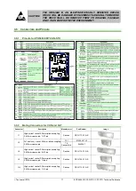
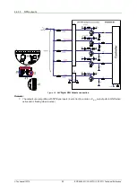
Страница 17: ...rs for CAN and CAT Connector Description Manufacturer Part Number Image J1 High current socket 2 54mm pitch accepting 0 635mm square pin 1x12 pin Samtec SSQ 112 01 G S J2 2x7 contacts socket 2 54mm pitch accepting 0 635mm square pin FCI 87606 307LF TE Connectivity 534206 7 J4 High current socket 2 54mm pitch accepting 0 635mm square pin 2x16 pin Samtec SSQ 116 01 G D J5 High current socket 2 54mm ...

Страница 18: ... Technosoft 2016 18 iPOS4808 MY CAN STO CAT STO Technical Reference 3 5 3 Pinouts for iPOS4808 MY CAT STO ...

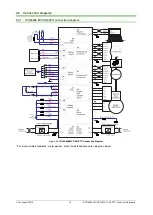
Страница 19: ...STO CAT STO Technical Reference 3 6 Connection diagrams 3 6 1 iPOS4808 MY CAN STO connection diagram Figure 3 4 iPOS4808 MY CAN STO Connection diagram For other available feedback motor options check the detailed connection diagrams below ...

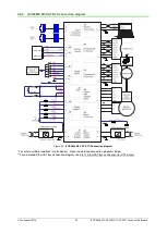
Страница 20: ... iPOS4808 MY CAT STO connection diagram Figure 3 5 iPOS4808 MY CAT STO Connection diagram For other available feedback motor options check the detailed connection diagrams below For a detailed EtherCAT bus connection diagram see 3 6 11 EtherCAT bus connection for CAT drives ...

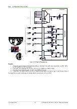
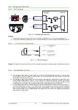
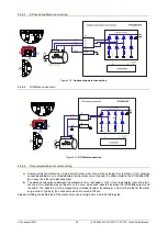
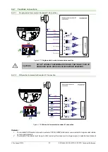
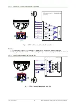
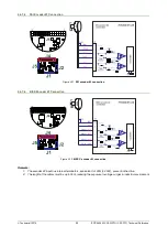
Страница 21: ...ive voltage value 5 36V to change its default state 3 The length of the cables must be up to 30m reducing the exposure to voltage surge in industrial environment 3 6 3 2 NPN inputs Figure 3 7 24V Digital NPN Inputs connection Remarks 1 The inputs are selectable as PNP NPN by software 2 The inputs are compatible with NPN type outputs input must be pulled to GND to change its default state 3 The len...

Страница 22: ...CAT STO Technical Reference 3 6 3 3 NPN outputs Figure 3 8 24V Digital NPN Outputs connection Remarks 1 The outputs are compatible with NPN type inputs load is tied to common VLOG output pulls to GND when active and is floating when inactive ...

Страница 23: ... 5V connection they are selected as PNP NPN is not compatible on a 5V connection 2 The inputs are compatible with TTL 5V LVTTL 3 3V CMOS 3 3V 24V outputs 3 The outputs are compatible with TTL 5V and CMOS 5V inputs 4 The length of the cables must be up to 30m reducing the exposure to voltage surges in industrial environment The output loads can be individually and independently connected to 5V or t...

Страница 24: ...ects the source ground to the drive ground shield will be connected to the drive ground terminal b If the analogue signal source is differential and the signal source ground is isolated from the drive GND use a 2 wire twisted shielded cable as follows 1st wire connects the source plus positive in phase to the drive analogue input 2nd wire connects the source minus negative out of phase to the driv...

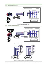
Страница 25: ...rence 3 6 6 Motor connections 3 6 6 1 Brushless Motor connection Figure 3 12 Brushless motor connection 3 6 6 2 2 phase Step Motor connection Figure 3 13 2 phase step motor connection one coil per phase Figure 3 14 2 phase step motor connection two coils per phase ...

Страница 26: ...ielded cable for the motor wires Connect the cable shield to the iPOS4808 GND pin Leave the other end disconnected b The parasitic capacitance between the motor wires must not bypass 10nF If very long cables tens of meters are used this condition may not be met In this case add series inductors between the iPOS4808 outputs and the cable The inductors must be magnetically shielded toroidal for exam...

Страница 27: ...ATED WIRES THEY MIGHT PICK UP UNWANTED NOISE AND GIVE FALSE ENCODER READINGS 3 6 7 2 Differential Incremental Encoder 1 Connection Figure 3 18 Differential incremental encoder 1 connection Remarks 1 For encoder 1 differential connection external 120Ω 0 25W terminators are required for long encoder cables or noisy environments 2 The length of the cables must be up to 30m reducing the exposure to vo...

Страница 28: ...al incremental encoder 2 connection Remarks 1 The encoder 2 input has internal terminators equivalent to 120Ω 0 25W present in the drive 2 The length of the cables must be up to 30m reducing the exposure to voltage surges in industrial environment 3 6 7 4 Sine Cosine Analog Encoder Connection Figure 3 20 Sine Cosine analogue encoder connection ...

Страница 29: ...1 SSI encoder 2 connection 3 6 7 6 BiSS Encoder 2 Connection Figure 3 22 BiSS C encoder 2 connection Remarks 1 The encoder 2 input has internal terminators equivalent to 120Ω 0 25W present in the drive 2 The length of the cables must be up to 30m reducing the exposure to voltage surges in industrial environment ...

Страница 30: ... device The actual motor control is done with an incremental encoder 2 The length of the cables must be up to 30m reducing the exposure to voltage surges in industrial environment 3 6 7 8 Digital Hall Connection for direct motor control without an encoder Figure 3 24 Digital Hall connection Remarks 1 This connection is required when using only Digital hall signals as the main feedback device for m...

Страница 31: ...d pair for the 5V supply and GND b Always use shielded cables to avoid capacitive coupled noise when using single ended encoders or Hall sensors with cable lengths over 1 meter Connect the cable shield to the GND at only one end This point could be either the iPOS4808 using the GND pin or the encoder motor Do not connect the shield at both ends c If the iPOS4808 5V supply output is used by another...

Страница 32: ...ires are longer than 2 meters use twisted wires for the supply and ground return For wires longer than 20 meters add a capacitor of at least 2 200μF rated at an appropriate voltage right on the terminals of the iPOS4808 3 6 8 3 Recommendations to limit over voltage during braking During abrupt motion brakes or reversals the regenerative energy is injected into the motor power supply This may cause...

Страница 33: ...ke shunt resistor RBR between phase BR B and ground and activate the software option of dynamic braking see below This option is not available when the drive is used with a step motor The dynamic braking option can be found in the Drive Setup dialogue within EasyMotion EasySetup The braking will occur when DC bus voltage increases over UBRAKE This parameter UBRAKE should be adjusted depending on t...

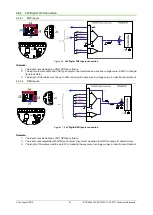
Страница 34: ...rval between braking cycles must be increased WARNING THE BRAKE SHUNT RESISTOR MAY HAVE HOT SURFACES DURING OPERATION 3 6 9 Serial RS 232 connection 3 6 9 1 Serial RS 232 connection Figure 3 27 Serial RS 232 connection 3 6 9 2 Recommendation for wiring a If you build the serial cable you can use a 3 wire shielded cable with shield connected to BOTH ends Do not use the shield as GND The ground wire...

Страница 35: ...ND The cable impedance must be 105 135 ohms 120 ohms typical and a capacitance below 30pF meter b When using a printed circuit board PCB motherboard based on FR 4 material build the CAN network using a pair of 12mil 0 012 tracks spaced 8 to 10mils 0 008 0 010 apart placed over a local ground plane microstrip which extends at least 1mm left and right to the tracks c Whenever possible use daisy chai...

Страница 36: ...chnical Reference 3 6 11 EtherCAT bus connection for CAT drives Figure 3 30 EtherCAT bus to RJ45 connection PoE compliant Figure 3 31 EtherCAT bus to M8 circular connection Figure 3 32 EtherCAT bus to RJ45 connection alternative non compliant with PoE ...

Страница 37: ... digital Hall inputs status Figure 3 33 Temporary connection during power on to remove the drive from Autorun mode 3 7 CAN Operation Mode and Axis ID Selection for CAN drives J1 pin settings The communication protocol as well as the Hardware Axis ID can be set by connecting J1 pins to GND ON connect pin to GND pin 1 OFF leave pin unconnected An 8 pole DIN switch can be connected to these pins on a...

Страница 38: ...itx The drive axis address number is set when H W is selected in Drive Setup under AxisID field or when the Setup is invalid The axis ID is an 8 bit unsigned number Its first 7 bits are controlled by the ID bit0 to ID bit6 Bit7 of this variable is always 0 In total 127 axis ID HW values can result from the DIP switch combinations When pins 3 9 remain unconnected the drive Axis ID will be 255 and c...

Страница 39: ...ased Protection degree According to IEC60529 UL508 IP20 3 9 5 Logic Supply Input VLOG Min Typ Max Units Supply voltage Nominal values 9 36 VDC Absolute maximum values drive operating but outside guaranteed parameters 8 40 VDC Absolute maximum values continuous 0 6 42 VDC Absolute maximum values surge duration 10ms 1 45 V VLOG 12V 130 mA VLOG 24V 90 280 VLOG 40V 85 3 9 6 Motor Supply Input VMOT Min...

Страница 40: ...0 FPWM 60 kHz 30 FPWM 80 kHz 15 FPWM 100 kHz 8 Motor electrical time constant L R Recommended value for 5 current measurement error due to ripple FPWM 20 kHz 250 µs FPWM 40 kHz 125 FPWM 60 kHz 100 FPWM 80 kHz 63 FPWM 100 kHz 50 Current measurement accuracy FS Full Scale 4 8 FS 3 9 8 Digital Inputs IN0 IN1 IN2 LSP IN3 LSN IN4 IN5 1 Min Typ Max Units Mode compliance PNP Default state Input floating ...

Страница 41: ...connected Logic HIGH Input voltage Logic LOW 0 0 8 V Logic HIGH 2 5 Floating voltage not connected 4 4 Absolute maximum surge duration 1s 10 15 Input current Logic LOW Pull to GND 1 2 mA Logic HIGH Internal 1KΩ pull up to 5 0 0 0 Minimum pulse width 2 µs ESD protection Human body model 5 kV 3 9 11 Encoder 1 Inputs A1 A1 B1 B1 Z1 Z1 1 Min Typ Max Units Single ended mode compliance Leave negative in...

Страница 42: ...ND 2 2 kΩ Resolution with interpolation Software selectable for one sine cosine period 2 10 bits Frequency Sin Cos interpolation 0 450 kHz Quadrature no interpolation 0 10 MHz ESD protection Human body model 2 kV 3 9 15 SSI encoder interface Min Typ Max Units Differential mode compliance CLOCK DATA 1 TIA EIA 422 CLOCK Output voltage Differential 50Ω differential load 2 0 2 5 5 0 V Common mode refe...

Страница 43: ...ution single turn or single turn multi turn 31 bit Protocol BiSS C mode sensor mode 3 9 17 Analog 0 5V Inputs REF FDBK Min Typ Max Units Input voltage Operational range 0 5 V Absolute maximum values continuous 12 18 Absolute maximum surge duration 1s 36 Input impedance To GND 30 kΩ Resolution 12 bits Integral linearity 2 bits Offset error 2 10 bits Gain error 1 3 FS1 Bandwidth 3dB Software selecta...

Страница 44: ...mA 3 3 output voltage 3 15 3 3 3 45 V 3 3 output current 60 mA 3 9 23 Safe Torque OFF STO1 STO1 STO2 STO2 Min Typ Max Units Safety function According to EN61800 5 2 STO Safe Torque OFF EN 61800 5 1 2 and EN 61508 5 3 4 Classification Safety Integrity Level safety integrity level 3 SIL3 PFHd Probability of Failures per Hour dangerous 8 10 10 hour 1 0 8 FIT EN13849 1 Classification Performance Level...

Страница 45: ...ring run time The E2 ROM is mapped in the address range 4000h to 7FFFh It is used to keep in a non volatile memory the TML programs the cam tables and the drive setup information Remark EasyMotion Studio handles automatically the memory allocation for each motion application The memory map can be accessed and modified from the main folder of each application Figure 7 1 iPOS4808 MY Memory Map TML P...

Отзывы: