RUN 600 XTPRO: Service & Maintenance Manual - rev. 1.3
Page 7.11
7.7. DISASSEMBLING THE HS INTERFACE BOARD
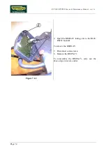
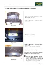
Figure 7.7-1
1. Turn off the machine and unplug the mains
lead from the wall output.
2. Back off the 8 screws
a
using a large Phillips
screwdriver.
Figure 7.7-2
3. Disconnect connectors
b
.
4. Disconnect connector
c
.
Figure 7.7-3
5. Back off the 2 screws
d
using a large Phillips
screwdriver.
6. Remove the HS INTERFACE BOARD.
7. To separate the circuit board from its
support, open the 4 fixing clips.
To reassemble the HS INTERFACE BOARD,
carry out the above steps in reverse order.
The cable which goes from the CPU
board to the HS interface board must be
plugged into the lowermost connector of
the HS interface board (looking at the
display from the exercise position).
Содержание RUN 600 XTPRO
Страница 1: ...SERVICE MAINTENANCE MANUAL REV 1 3...
Страница 2: ......
Страница 4: ......
Страница 24: ...RUN 600 XTPRO Service Maintenance Manual rev 1 3 Page 2 14 Page intentionally left blank...
Страница 36: ...RUN 600 XTPRO Service Maintenance Manual rev 1 3 Page 3 12 Page intentionally left blank...
Страница 38: ...RUN 600 XTPRO Service Maintenance Manual rev 1 3 Page 4 2 Page intentionally left blank...
Страница 82: ...RUN 600 XTPRO Service Maintenance Manual rev 1 3 Page 6 42 Page intentionally left blank...
Страница 126: ...RUN 600 XTPRO Service Maintenance Manual rev 1 3 Page 8 10 Page intentionally left blank...
Страница 156: ...RUN 600 XTPRO Service Maintenance Manual rev 1 3 Page 11 14 Page intentionally left blank...
Страница 157: ......


