RUN 600 XTPRO: Service & Maintenance Manual - rev. 1.3
Page 6.35
(3)
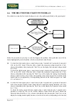
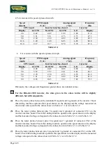
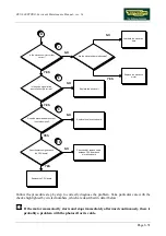
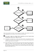
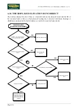
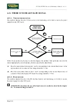
If the machine fails to move downward, place the tester probes between pins 12 (ground) and
11 (signal) of connector CN1 on the CPU board: the measured voltage should be
approximately 4.2 Vdc. If the machine fails to move upward, place the tester probes between
pins 12 (ground) and 10 (signal) of connector CN1 on the CPU board: the measured voltage
should be approximately 4.2 Vdc.
(4)
DL1 corresponds to the upper limit switch, while DL2 on SMD board / DL3 on traditional
board corresponds to the lower limit switch.
(5)
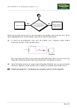
Disconnect the 2 connecting cables of the relevant limit switch and place the tester probes
across them: the measured voltage should be approximately 12 Vdc.
(6)
To check the upper limit switch, place the tester probes between pins 6 (ground) and 3 (signal)
of connector CN3 on the elevation board.: the measured voltage should be 12 Vdc. To check
the lower limit switch, place the tester probes between pins 6 (ground) and 4 (signal) of
connector CN3 on the elevation board: the measured voltage should be 12 Vdc.
Содержание RUN 600 XTPRO
Страница 1: ...SERVICE MAINTENANCE MANUAL REV 1 3...
Страница 2: ......
Страница 4: ......
Страница 24: ...RUN 600 XTPRO Service Maintenance Manual rev 1 3 Page 2 14 Page intentionally left blank...
Страница 36: ...RUN 600 XTPRO Service Maintenance Manual rev 1 3 Page 3 12 Page intentionally left blank...
Страница 38: ...RUN 600 XTPRO Service Maintenance Manual rev 1 3 Page 4 2 Page intentionally left blank...
Страница 82: ...RUN 600 XTPRO Service Maintenance Manual rev 1 3 Page 6 42 Page intentionally left blank...
Страница 126: ...RUN 600 XTPRO Service Maintenance Manual rev 1 3 Page 8 10 Page intentionally left blank...
Страница 156: ...RUN 600 XTPRO Service Maintenance Manual rev 1 3 Page 11 14 Page intentionally left blank...
Страница 157: ......


