RUN 600 XTPRO: Service & Maintenance Manual - rev. 1.3
Page 3.4
•
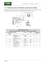
Hitachi J100
:
installed up until serial number 01000078;
•
Hitachi SJ100
: on actual production.
The inverter has a power of 1.5 KW (2 Hp).
3.1.9. I
NVERTER INTERFACE BOARD
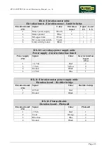
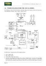
Receives from the display an enable signal for the inverter and a PWM signal proportional to the
selected speed, and converts it into a continuous voltage for controlling the inverter. Receives the
error signal generated by the inverter in the event of problems and transmits it to the display.
Receives the low voltages output by the power supply and passes them to the display. There are 2
LEDs on the board:
•
DL1
: illuminates when the tread belt is moving;
•
DL2
: illuminates when the inverter does not detect any error conditions and therefore the alarm
signal is inactive.
3.1.10. E
LEVATION MOTOR
It is a DC motor which, by means of a mechanical reduction unit and a timing belt, turns the lead
screw nuts on the threaded elevation bars, causing the machine to be raised or lowered depending on
the direction of rotation.
3.1.11. P
HOTOCELL
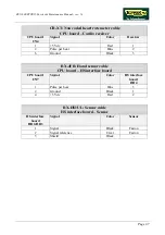
This is the device which provides feedback on the motion of the elevation motor. It transmits one
pulse for each tooth detected on the encoder wheel which is fixed to the gearmotor, and a signal
indicating the direction of movement.
The photocell used on these machines is the
Optek OPB610
photocell mounted on circuit board
GF970711
.
3.1.12. E
LEVATION BOARD
Receives from the display the enable signal for elevation motion and converts it into a control for
the elevation motor. Generates its power supply and the DC power supply for the motor by means of
a transformer and rectifier bridge. Determines the motor position, and hence the treadmill elevation,
by means of the photocell. Generates and sends to the display a motion status signal at every 0.5%
variation in the elevation.
The SW version of the chip mounted on the board to be used is
RX50V1
and is identified by the
label on the chip.
It checks the lower and upper travel limits by means of 2 limit switches. The board includes 2 LEDs
associated to the limit switches, which are normally illuminated:
•
DL1
: comes off when the upper limit switch is tripped;
•
DL2
: comes off if the lower limit switch is tripped.
Содержание RUN 600 XTPRO
Страница 1: ...SERVICE MAINTENANCE MANUAL REV 1 3...
Страница 2: ......
Страница 4: ......
Страница 24: ...RUN 600 XTPRO Service Maintenance Manual rev 1 3 Page 2 14 Page intentionally left blank...
Страница 36: ...RUN 600 XTPRO Service Maintenance Manual rev 1 3 Page 3 12 Page intentionally left blank...
Страница 38: ...RUN 600 XTPRO Service Maintenance Manual rev 1 3 Page 4 2 Page intentionally left blank...
Страница 82: ...RUN 600 XTPRO Service Maintenance Manual rev 1 3 Page 6 42 Page intentionally left blank...
Страница 126: ...RUN 600 XTPRO Service Maintenance Manual rev 1 3 Page 8 10 Page intentionally left blank...
Страница 156: ...RUN 600 XTPRO Service Maintenance Manual rev 1 3 Page 11 14 Page intentionally left blank...
Страница 157: ......


