2-2
EO18-33007
2. MAJOR UNIT REPLACEMENT
2.1 REPLACING THE CPU PC BOARD
2.1 REPLACING THE CPU PC BOARD
CAUTION:
Replace only with the same type and rated fuse for continued protection against risk of fire.
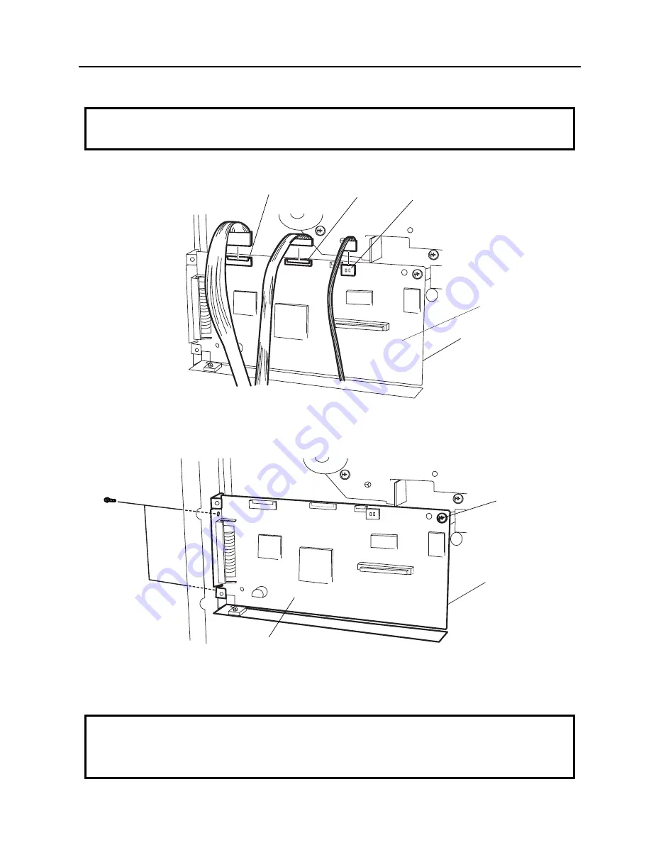
1) Disconnect the 3 harnesses from CN2, CN5, and CN7 on the CPU PC Board.
Fig. 2-2
CAUTION:
Be careful when replacing the CPU PC board, since a non-resettable counter (IC15) is installed on
this board. (Refer to section 6.2.1 Maintenance Counter Printing.) If this counter should be reset,
replace IC15.
Fig. 2-3
2) Remove the 3 screws (SM-3x5 and SM-3x6) to detach the CPU PC board.
3) Replace the CPU PC board and reassemble in the reverse order of removal.
CPU PC Board
CN2
CN5
CN7
CPU PC Board
SM-3x5 Screw
SM-3x6 Screw
Содержание B-880 series
Страница 3: ...TEC Thermal Printer B 870 880 QQ SERIES Owner s Manual ...
Страница 35: ......
Страница 36: ...PRINTED IN JAPAN EO1 33017 ...
Страница 56: ......
Страница 57: ......
Страница 58: ...PRINTED IN JAPAN EO10 33008 ...
Страница 146: ...6 59 6 DIAG TEST OPERATION EO18 33007 Fig 6 25 Bar code AUTO PRINT Fig 6 24 ...
Страница 176: ......
Страница 177: ......
Страница 178: ...PRINTED IN JAPAN EO18 33007 ...
Страница 179: ......
Страница 180: ......


