background image

OPERATING PROCEDURES

6-13 

Models 345, 346, 349, 355 

Operating Procedures 

 6

6. Raise the prime plug. Place an empty pail under the 

door spout. When cleaning solution begins to exit the 
relief port opening in the freezer door, lower the 
prime plug. Press the OFF key. Open the draw valve 
and relieve all pressure from the freezing cylinder. 
Remove the hopper cover. Remove the mix feed tube 
and take it to the sink for further cleaning. Close the 
prime plug.

7. Prepare a pail of approved 100 PPM cleaning 

solution (examples: 2-1/2 gal. [9.5 L] of Kay-5

®

 or 2 

gal. [7.6 L] of Stera-Sheen

®

). Use warm water and 

follow the manufacturer’s specifications.

8. Slowly pour the cleaning solution into the mix hopper 

until the hopper becomes 1/4 full of cleaning solution.

9. With the brushes provided, brush-clean the mix 

hopper, mix inlet hole, mix level float switch, and 
product fitting.

Important! 

Use caution when cleaning the float 

switch. Failure to do so will cause damage to the 

component.

10. Clean and install the hopper cover. Lock the cover 

into place. Attach the vinyl tube to the pressure relief 
valve on the hopper cover. Position the open end of 
the vinyl tube into the rear drip pan.

11. Press the BEATER key to agitate the solution in the 

freezing cylinder.

12. With a pail beneath the door spout, open the draw 

valve and drain all the solution from the mix hopper 
and the freezing cylinder. Press the OFF key and 
close the draw valve.

13. Disconnect the syrup connector.

14.

Repeat step 2 through step 13 

for the remaining 

freezing cylinder(s).

Disassembly

1. Make sure the control switch is in the OFF position. 

Open the draw valves to make sure all pressure has 
been relieved.

2. Raise the prime plug. Leave the bleed port open 

when removing the freezer door to  make sure all 
pressure is relieved from the freezing cylinder.

3. Remove the following parts from the freezer, and 

take them to the sink for brush-cleaning: handscrews, 
freezer doors, baffle assemblies, beater assemblies, 
scraper blades, drive shafts, hopper covers, front drip 
tray, and splash shield.

Brush Cleaning

1. Prepare a sink with an approved cleaning solution. 

(examples: Kay-5

®

 or Stera-Sheen

®

). Use warm 

water and follow the manufacturer’s specifications. 

Important! 

Follow the label directions. Too 

strong

 of 

a solution can cause parts damage, while too 

mild

 of 

a solution will not provide adequate cleaning. Make 

sure all brushes provided with the freezer are 

available for brush cleaning.

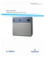
2. Return to the freezer with a small amount of cleaning 

solution. With a single-service towel, wipe clean the 
bearing surface. Brush-clean the rear shell bearings 
at the back of the freezing cylinders with the black 
bristle brush.

Figure 6-49

10228

Содержание 345

Страница 1: ...OPERATOR S MANUAL Model 345 346 349 355 Slush Freezers 06 19 01 Original Publication Updated 2 4 2019 Original Operating Instructions 039710 M...

Страница 2: ...__________ Phase__________________________________ Maximum Fuse Size ______________________________________________________ A Minimum Wire Ampacity ___________________________________________________...

Страница 3: ...on 3 Safety Section 4 Operator Parts Identification Section 5 User Interface Symbol Definitions Model 349 Only 5 2 Control Switch 5 2 Liquid Crystal Display 5 2 Operational Mode Display 5 2 Operator M...

Страница 4: ...eezing Cylinder 6 12 Cleaning 6 12 Disassembly 6 13 Brush Cleaning 6 13 Section 7 Operator Checklist During Cleaning and Sanitizing 7 1 Troubleshooting Bacterial Count 7 1 Regular Maintenance Checks 7...

Страница 5: ...rior to performing any installation maintenance or repairs Failure to follow this instruction may result in personal injury or death from electrical shock or hazardous moving parts as well as poor per...

Страница 6: ...stments may cause operation discrepancies IMPORTANT A backflow prevention device is required on the incoming water connection side Please see the applicable national state and local codes for determin...

Страница 7: ...IMPORTANT Stationary machines which are not equipped with a power cord and a plug or another device to disconnect the machine from the power source must have an all pole disconnecting device with a co...

Страница 8: ...through a manufacturer s technical bulletin The use of any other refrigerant may expose users and operators to unexpected safety hazards IMPORTANT Refrigerants and their associated lubricants may be...

Страница 9: ...yrup to the left syrup sentry Note For Bag in Box BIB machines connect the 1 line to the Bag in Box instead of the syrup tank Figure 1 3 c Connect the 2 line to the syrup tank or the Bag in Box for th...

Страница 10: ...psi 4 1 bar The secondary regulator located inside the freezer just behind the primary regulator can be adjusted from 20 psi to 25 psi 1 38 bar to 1 72 bar The factory recommendation is 20 psi 1 38 ba...

Страница 11: ...warranty is valid only if the parts are authorized Taylor parts purchased from the local authorized Taylor distributor and only if all required service work is provided by an authorized Taylor servic...

Страница 12: ...this fact known to any technician he or she employs It should also be noted that Taylor does not warrant the refrigerant used in its equipment For example if the refrigerant is lost during the course...

Страница 13: ...ne Failure to follow these instructions may result in serious electrical shock WARNING Avoid injury DO NOT operate the machine unless it is properly grounded DO NOT operate the machine with larger fus...

Страница 14: ...T Access to the service area of the machine must be restricted to persons having knowledge and practical experience with the machine in particular as far as safety and hygiene are concerned NOTICE Cle...

Страница 15: ...e has been relieved by opening the draw valve Failure to follow these instructions may result in severe personal injury from hazardous moving parts or from the impact of propelled parts WARNING Only i...

Страница 16: ...3 4 SAFETY Models 345 346 349 355 Safety 3 Notes...

Страница 17: ...3 4 10 Stem 021279 6 Caster 3 SWV w Brake 030307 7 Lock Caster BRKT 032571 8 Shield Splash 043719 9 Tray Drip Black w Drain 043720 SP 10 Pan Drip 19 1 2 Long 035034 11 Panel Service 044916 Item Descri...

Страница 18: ...0307 7 Lock Caster Bracket 032571 8 Shield Splash 043719 9 Tray Drip Black w Drain 043720 SP 10 Pan Drip 19 1 2 Long 035034 11 Panel Service 346 Filter 053612 Item Description Part No 12 Panel Front L...

Страница 19: ...Caster 3 SWV w Brake 030307 7 Lock Caster BRKT 032571 8 Panel Service 053652 9 Tray Drip Black w Drain 038275 SP 10 Shield Splash 038276 11 Panel Front Lower BLK 042082 BLA Item Description Part No 1...

Страница 20: ...l Rear Stainless 044621 SS 5 Panel Side Right 044620 SP 6 Leg 4 3 8 6 Stud 036397 7 Shelf Drip Tray 049697 8 Tray Drip Black w o Drain 043720 9 Shield Splash 043719 Item Description Part No 10 Pan Dri...

Страница 21: ...1e Spout Door FCB Black 046190 BLA 1f Handle Draw FCB Black 046192 BLA 1g Pin Pivot Spout Door 039321 1h Slide Handle Door BLK 046193 BLA 1i Screw 10 32X3 8PHL TRUS 053869 1j O ring 9 32 OD X 1 16 Wa...

Страница 22: ...r Stera Sheen part no 055492 100 2 oz packs or Kay 5 part no 041082 200 packs Accessories Item Description Part No 1 Pail 10 qt 013163 2 Brush Mix Pump Body 3 X7 023316 3 Brush Double Ended 013072 4 B...

Страница 23: ...6 349 355 User Interface 5 User Interface Figure 5 1 1 2 3 5 6 4 Item Description 1 Control Switch 2 Liquid Crystal Display LCD 3 Keypad Left Item Description 4 Keypad Right 5 Product Light Left Side...

Страница 24: ...If an error in the machine operation occurs a warning tone will sound and the word FAULT will flash on the third line of the display Operational Mode Display When the machine is plugged into the wall...

Страница 25: ...ions are apparent Note On Model 349 faults for freezing cylinders one and two are shown on the first screen Press the SELECT key to read fault messages for freezing cylinders three and four 2 BEATER O...

Страница 26: ...freezing cylinder enters the Auto mode the control will check product temperature After 5 minutes it will again check product temperature If product temperature does not drop in that 5 minute time sp...

Страница 27: ...nd will be executed 2 Repeat step 1 for the right side of the machine Note Models 345 and 355 allow only one freezing cylinder to be defrosted at a time This applies to freezing cylinder pairs on the...

Страница 28: ...screen will appear This example shows that all seven days have CYCLE 1 programmed for 9 00 Press the or keys to view other cycles If one or more days of the week have a given cycle programmed at diff...

Страница 29: ...ows the authorized service technician to access service information Return to the OPERATOR MENU by using the arrow keys to move the cursor under the letter A and press the MENU SELECT key Syrup Out In...

Страница 30: ...lencer The audio alarm will be disabled if the ALARM SILENCE key is pressed If a new fault or fault condition occurs or the system mode changes the audio alarm will be re enabled automatically If the...

Страница 31: ...he mix hoppers As product is drawn new product from the hopper will flow through a mix feed tube down into the freezing cylinder The mix hopper is supplied with 20 lb of CO2 gas for dispensing the fin...

Страница 32: ...in the door spout This may contaminate the product and cause severe personal injury from blade contact USE EXTREME CAUTION when removing the beater assembly The scraper blades are very sharp 5 Install...

Страница 33: ...Lubricate the O rings and the valve as illustrated below Figure 6 8 Insert the draw valve into the freezer door spout from the front of the machine The valve is properly installed when the hole in th...

Страница 34: ...e the threaded cap on the end of the draw valve cavity Turn the cap clockwise until it is secure Figure 6 14 11 Install the prime plug Place the two O rings on the prime plug and lightly lubricate Fig...

Страница 35: ...to ensure that the door is secure Do not over tighten the handscrews Figure 6 18 15 Place the O ring into the groove of the hopper cover Figure 6 19 Install the hopper cover Lock it into place Figure...

Страница 36: ...en Use warm water and follow the manufacturer s specifications Important Make sure the sanitizer is completely dissolved For Bag in Box Units follow steps 3 through 5 3 Using an empty bag of syrup cut...

Страница 37: ...tizing solution begins to exit the relief port opening in the freezer door lower the prime plug Press the OFF key Figure 6 28 10 Prepare a pail of approved 100 PPM sanitizing solution examples 2 1 2 g...

Страница 38: ...345 346 349 355 Operating Procedures 6 Figure 6 30 Figure 6 31 Figure 6 32 Figure 6 33 Figure 6 34 13 Install the mix feed tube into the mix inlet hole in the bottom of the mix hopper Figure 6 35 1209...

Страница 39: ...s the BEATER key Agitate the solution in the freezing cylinder for 5 minutes Figure 6 37 16 With a pail beneath the door spout open the draw valve and drain all the solution from the mix hopper and th...

Страница 40: ...allow a slight hissing sound Figure 6 41 Note The pressure in the freezing cylinder should be relieved slowly 4 Slowly open the syrup sampling valve and let it run into a pail until all the sanitizer...

Страница 41: ...d close the sampling valve Install the front drip tray and the splash shield on the front of the freezer Figure 6 45 7 With a pail beneath the door spout press the BEATER key Open the draw valve and d...

Страница 42: ...emaining freezing cylinder s Cleaning 1 Open the lighted display door from the front of the machine Remove the hood and side panels to gain access to the hoppers 2 Prepare a pail of approved 100 PPM c...

Страница 43: ...der 12 With a pail beneath the door spout open the draw valve and drain all the solution from the mix hopper and the freezing cylinder Press the OFF key and close the draw valve 13 Disconnect the syru...

Страница 44: ...ings from freezer doors O rings from mix hopper covers Discard all O rings and replace them with new ones Note To remove O rings use a single service towel to grasp the O ring Apply pressure in an upw...

Страница 45: ...ant and product deposits Properly prepare the cleaning and sanitizing solutions Read and follow the label directions carefully Too strong of a solution may damage the parts and too weak of a solution...

Страница 46: ...Taylor distributor can perform this service for you Wrap detachable parts of the freezer such as the beater scraper blades drive shaft and freezer door and place them in a protected dry place Rubber...

Страница 47: ...reen c Allow the motor to cool Press the AUTO key Contact a service technician if the beater motor goes out on overload again 5 3 5 No compressor operation in the Auto mode a Beater motor is out on ov...

Страница 48: ...s b Blocked flow control b Contact a service technician 11 Lack of syrup being supplied to machine a Loss of CO2 to propel syrup a Contact a service technician b Clogged or kinked syrup lines b Saniti...

Страница 49: ...ive Shaft O ring X Freezer Door O ring X Draw Valve O ring X Door Spout O ring X Hopper Cover O ring X Front Bearing X Prime Plug O Ring X White Bristle Brush 3 x 7 Inspect and replace if necessary Mi...

Страница 50: ...9 2 PARTS REPLACEMENT SCHEDULE Models 345 346 349 355 Parts Replacement Schedule 9 Notes...

Страница 51: ...ay be required at time of service 2 This limited warranty is valid only if the Product is installed and all required service work on the Product is performed by an authorized Taylor distributor or ser...

Страница 52: ...refrigerant other than that specified on the Product s data label will void this limited warranty 13 Any cost to replace refill or dispose of refrigerant including the cost of refrigerant 14 ANY SPEC...

Страница 53: ...verified proof of purchase may be required at time of service 2 This limited warranty is valid only if the Part is installed and all required service work in connection with the Part is performed by a...

Страница 54: ...ning warranty service work promptly upon arrival 9 Failure damage or repairs due to faulty installation misapplication abuse no or improper servicing unauthorized alteration or improper operation or u...

Страница 55: ...L OR INCIDENTAL DAMAGES INCLUDING CLAIMS FOR LOST SALES LOST PROFITS PRODUCT LOSS PROPERTY DAMAGES OR SERVICE EXPENSES ARE EXPRESSLY EXCLUDED THE EXPRESS WARRANTIES MADE IN THIS LIMITED WARRANTY MAY N...

Страница 56: ...11 4 LIMITED WARRANTY ON PARTS Models 345 346 349 355 Limited Warranty on Parts 11 Notes...

Отзывы: