


Maintenance, Service, and Repair
Steering
Page 18
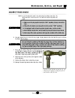
CENTER THE STEERING GEAR
1.
Remove the pitman arm.
2.
Rotate the input shaft clockwise until it stops.
3.
While counting the rotations, rotate the input shaft counter clockwise until it stops.
4.
Rotate the input shaft clockwise 1/2 the rotations counted in the previous step.
5.
Mark the steering gear input shaft and pitman shaft in relation to the housing for reference.
PITMAN SHAFT ALIGNMENT
1. Make sure the key-switch is in the “OFF” position, then remove the
key.
2. Place the forward-reverse switch in the center “OFF” position.
3. If equipped with a hand operated park brake, set the brake.
4. Place blocks under the rear wheels to prevent vehicle movement.
5. Disconnect the main positive and negative cables at the batteries.
Always use a lifting strap, hoist, and jack stands, of adequate capacity
to lift and support the vehicle. Failure to use lifting and support devices
of rated load capacity may result in severe bodily injury.
6. Raise the front of the vehicle and support with jack stands.
7. Center the steering gear. Refer to
Center the Steering Gear
section for information regarding
centering the steering gear.
8. Screw both steering stops all of the way in.
9. Install the pitman arm so that it is centered between the steering stops.
10. Realign the front wheels. Refer to
Front End Alignment
section for information regarding
aligning the front wheels.
11. Adjust the steering stops so that the front wheels do not contact any part of the frame, suspension
or steering linkages and the left and right turning radiuses are equal.
12. Tighten the steering stop jam nuts.
13. Lower the vehicle.
14. Reconnect the main positive and negative cables at the batteries.
15. Remove the blocks from behind the wheels.
16. Release the park brake and test drive the vehicle.
Содержание B0-T48-48 Taylor Truck T48
Страница 2: ......
Страница 14: ...TAYLOR DUNN...
Страница 30: ...TAYLOR DUNN...
Страница 31: ...TABLE OF CONTENTS General Maintenance Maintenance Guidelines 2 Troubleshooting Guide 3 Lubrication Chart 4...
Страница 68: ...Maintenance Service and Repair Steering Page 22 Exploded View of Steering Gear...
Страница 86: ...TAYLOR DUNN...
Страница 106: ...Maintenance Service and Repair Transmission Page 20 NOTE Values shown are for reference only C D...
Страница 112: ...TAYLOR DUNN...
Страница 118: ...TAYLOR DUNN...
Страница 130: ...TAYLOR DUNN...
Страница 140: ...TAYLOR DUNN...
Страница 152: ...Illustrated Parts Parts Page 2 Front Axle...
Страница 154: ...Illustrated Parts Parts Page 4 Steering Knuckle...
Страница 156: ...Illustrated Parts Parts Page 6 Steering Linkage...
Страница 162: ...Illustrated Parts Parts Page 12 Rear Suspension View from rear...
Страница 164: ...Illustrated Parts Parts Page 14 Transmission Gear Case...
Страница 168: ...Illustrated Parts Parts Page 18 Rear Brakes Front Brakes...
Страница 170: ...Illustrated Parts Parts Page 20 Brake Lines and Master Cylinder...
Страница 172: ...Illustrated Parts Parts Page 22 Motor...
Страница 174: ...Illustrated Parts Parts Page 24 Motor Mount Apply 94 421 34 grease to inside of motor coupler...
Страница 180: ...Illustrated Parts Parts Page 30 Speed Control Panel Illustration not available at time of printing...
Страница 186: ...Illustrated Parts Parts Page 36 Batteries FRONT OF VEHICLE...
Страница 188: ...TAYLOR DUNN...


