


Maintenance, Service, and Repair
Tires and Wheels
Page 3
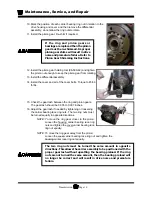
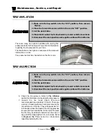
8. Inspect for uneven tire wear on the front tires. Uneven tire wear could be a result of an improperly
inflated tire or a misaligned or damaged front end.
NOTE: Refer to
Tire Inflation
section or
Steering Component Service
section for information on proper tire inflation or front end wheel
alignment.
9. Inspect the inner and outer side walls for cracks. If any cracks are seen, then the tire should be
replaced. Refer to
Replace the Tire
section for information regarding replacing the tire.
10. Inspect the valve stem for cracks. If any cracks are seen, then the valve stem should be replaced.
It is also recommended that the valve stem be replaced whenever the tire is replaced.
NOTE: Refer to
Replace the Tire
section for information regarding
replacing the valve stem.
11. Inspect the tread and side walls for debris in the rubber that could lead to a puncture. If any
debris is found it should be removed and the tire inspected for a leak.
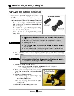
1. Make sure the key-switch is in the “OFF” position, then remove
the key.
2. Place the forward-reverse switch in the center “OFF” position.
3. Set the park brake.
4. Place blocks under the front wheels to prevent vehicle movement.
5. Disconnect the main positive and negative cables at the batteries.
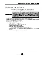
REPLACE THE TIRE/WHEEL
6. Raise the wheel to be replaced off of the ground and support with jack stands.
7. Remove the 4 or 5 wheel nuts and remove the wheel.
8. Install in reverse order.
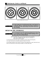
9. Following the pattern shown on the following page, cross tighten the wheel nuts in two stages as
follows:
1st stage to approximately 20 ft-lbs.
2nd stage to 80-90 ft-lbs.
10. Reconnect the main positive and negative cables at the batteries.
11. Lower the wheel to the ground.
12. Remove the blocks from behind the wheels.
13. Release the parking brake and test drive the vehicle.
Содержание B0-T48-48 Taylor Truck T48
Страница 2: ......
Страница 14: ...TAYLOR DUNN...
Страница 30: ...TAYLOR DUNN...
Страница 31: ...TABLE OF CONTENTS General Maintenance Maintenance Guidelines 2 Troubleshooting Guide 3 Lubrication Chart 4...
Страница 68: ...Maintenance Service and Repair Steering Page 22 Exploded View of Steering Gear...
Страница 86: ...TAYLOR DUNN...
Страница 106: ...Maintenance Service and Repair Transmission Page 20 NOTE Values shown are for reference only C D...
Страница 112: ...TAYLOR DUNN...
Страница 118: ...TAYLOR DUNN...
Страница 130: ...TAYLOR DUNN...
Страница 140: ...TAYLOR DUNN...
Страница 152: ...Illustrated Parts Parts Page 2 Front Axle...
Страница 154: ...Illustrated Parts Parts Page 4 Steering Knuckle...
Страница 156: ...Illustrated Parts Parts Page 6 Steering Linkage...
Страница 162: ...Illustrated Parts Parts Page 12 Rear Suspension View from rear...
Страница 164: ...Illustrated Parts Parts Page 14 Transmission Gear Case...
Страница 168: ...Illustrated Parts Parts Page 18 Rear Brakes Front Brakes...
Страница 170: ...Illustrated Parts Parts Page 20 Brake Lines and Master Cylinder...
Страница 172: ...Illustrated Parts Parts Page 22 Motor...
Страница 174: ...Illustrated Parts Parts Page 24 Motor Mount Apply 94 421 34 grease to inside of motor coupler...
Страница 180: ...Illustrated Parts Parts Page 30 Speed Control Panel Illustration not available at time of printing...
Страница 186: ...Illustrated Parts Parts Page 36 Batteries FRONT OF VEHICLE...
Страница 188: ...TAYLOR DUNN...


