


Maintenance, Service, and Repair
Transmission
Page 15
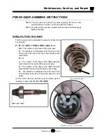
ASSEMBLING THE 3RD MEMBER
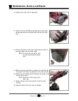
1. Temporarily install the pinion gear
(hand tighten only).
2. Install the carrier bearing race ring
nuts into the housing and cover.
3. Install the carrier bearing races into
the housing and cover.
Cover
Housing
Cover
Housing
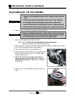
4. Place the differential assembly into the housing.
5. Tighten the housing carrier bearing race ring nut so that
the ring gear is not in binding against the pinion gear.
6. Remove the differential assembly.
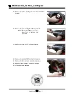
NOTE: Do not allow the ring nut to rotate.
7. Remove the pinion gear and then reinstall the
differential assembly.
8. Install the cover onto the housing using 4-bolts in a
cross pattern and torque to 45-50 ft-lbs.
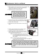
9. Pre set the carrier bearing preload by tightening the
housing carrier bearing race ring nut until it requires
1.5 to 3.3 ft-lbs to rotate the differential assembly.
NOTE: Rotate the carrier assembly whenever
adjusting the ring nuts.
Содержание B0-T48-48 Taylor Truck T48
Страница 2: ......
Страница 14: ...TAYLOR DUNN...
Страница 30: ...TAYLOR DUNN...
Страница 31: ...TABLE OF CONTENTS General Maintenance Maintenance Guidelines 2 Troubleshooting Guide 3 Lubrication Chart 4...
Страница 68: ...Maintenance Service and Repair Steering Page 22 Exploded View of Steering Gear...
Страница 86: ...TAYLOR DUNN...
Страница 106: ...Maintenance Service and Repair Transmission Page 20 NOTE Values shown are for reference only C D...
Страница 112: ...TAYLOR DUNN...
Страница 118: ...TAYLOR DUNN...
Страница 130: ...TAYLOR DUNN...
Страница 140: ...TAYLOR DUNN...
Страница 152: ...Illustrated Parts Parts Page 2 Front Axle...
Страница 154: ...Illustrated Parts Parts Page 4 Steering Knuckle...
Страница 156: ...Illustrated Parts Parts Page 6 Steering Linkage...
Страница 162: ...Illustrated Parts Parts Page 12 Rear Suspension View from rear...
Страница 164: ...Illustrated Parts Parts Page 14 Transmission Gear Case...
Страница 168: ...Illustrated Parts Parts Page 18 Rear Brakes Front Brakes...
Страница 170: ...Illustrated Parts Parts Page 20 Brake Lines and Master Cylinder...
Страница 172: ...Illustrated Parts Parts Page 22 Motor...
Страница 174: ...Illustrated Parts Parts Page 24 Motor Mount Apply 94 421 34 grease to inside of motor coupler...
Страница 180: ...Illustrated Parts Parts Page 30 Speed Control Panel Illustration not available at time of printing...
Страница 186: ...Illustrated Parts Parts Page 36 Batteries FRONT OF VEHICLE...
Страница 188: ...TAYLOR DUNN...


