


Maintenance, Service, and Repair
Steering
Page 3
10. At this point both the steering wheel
and
the front wheels should be tied up and held in position.
If one or the other is not tied up then you must start from the beginning.
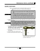
11. Loosen the ball joint clamps or the rod end jam nuts
on the drag link.
NOTE: Remember the position and orientation
of the clamps.
12. Adjust the drag link so that it can be easily inserted
into the pitman arm.
13. Tighten the ball joint or rod end nut as specified
below:
Ball joint - 40-45 ft-lbs.
Rod end - 20-25 ft-lbs.
14. If equipped with ball joints, position the ball joint
clamps in their original location and orientation.
15. Tighten the ball joint clamps (28-32 ft. lbs.) or the rod end jam nuts on the drag link.
16. Untie the steering wheel and the front wheels.
17. Reconnect the main positive and negative cables at the batteries.
18. Rotate the steering wheel from a full left turn to a full right turn and make sure that the ball joint
clamps do not contact any other component.
Do not drive the vehicle while the steering wheel or front wheels are
tied in position. Driving the vehicle while the steering wheel or front
wheels tied in the position may cause loss of control of the vehicle
resulting in severe bodily injury and/or property damage.
If the clamps are positioned so that they contact other components,
it may result in steering failure and loss of control of the vehicle
causing property damage and/or severe bodily injury.
19. Remove the blocks from behind the wheels.
20. Release the parking brake and test drive the vehicle.
T
A Y
L OR - DU N
N
T
he
B
e
st
W
ay
To
Go About
Yo
ur
Bu
si
n
e
ss
R
Содержание B0-T48-48 Taylor Truck T48
Страница 2: ......
Страница 14: ...TAYLOR DUNN...
Страница 30: ...TAYLOR DUNN...
Страница 31: ...TABLE OF CONTENTS General Maintenance Maintenance Guidelines 2 Troubleshooting Guide 3 Lubrication Chart 4...
Страница 68: ...Maintenance Service and Repair Steering Page 22 Exploded View of Steering Gear...
Страница 86: ...TAYLOR DUNN...
Страница 106: ...Maintenance Service and Repair Transmission Page 20 NOTE Values shown are for reference only C D...
Страница 112: ...TAYLOR DUNN...
Страница 118: ...TAYLOR DUNN...
Страница 130: ...TAYLOR DUNN...
Страница 140: ...TAYLOR DUNN...
Страница 152: ...Illustrated Parts Parts Page 2 Front Axle...
Страница 154: ...Illustrated Parts Parts Page 4 Steering Knuckle...
Страница 156: ...Illustrated Parts Parts Page 6 Steering Linkage...
Страница 162: ...Illustrated Parts Parts Page 12 Rear Suspension View from rear...
Страница 164: ...Illustrated Parts Parts Page 14 Transmission Gear Case...
Страница 168: ...Illustrated Parts Parts Page 18 Rear Brakes Front Brakes...
Страница 170: ...Illustrated Parts Parts Page 20 Brake Lines and Master Cylinder...
Страница 172: ...Illustrated Parts Parts Page 22 Motor...
Страница 174: ...Illustrated Parts Parts Page 24 Motor Mount Apply 94 421 34 grease to inside of motor coupler...
Страница 180: ...Illustrated Parts Parts Page 30 Speed Control Panel Illustration not available at time of printing...
Страница 186: ...Illustrated Parts Parts Page 36 Batteries FRONT OF VEHICLE...
Страница 188: ...TAYLOR DUNN...


