


1 – 47
Chapter 1 Troubleshooting
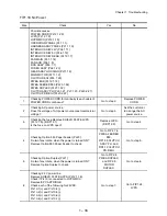
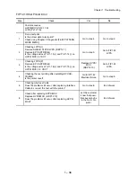
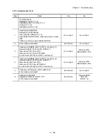
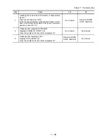
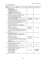
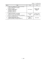
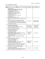
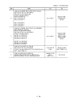
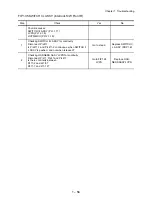
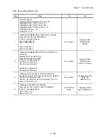
FIP1.28 SENSOR REGI
Step Check
Yes
No
Possible causes:
SENSOR REGI (PL5.1.30)
ACTUATOR B (PL5.1.17)
150 FEEDER ASSY (PL5.1.1)
HARNESS ASSY TRAY1 (PL5.1.37)
HARNESS ASSY CHUTE (PL12.1.17)
HVPS/MCU (PL12.1.19) LVPS (PL12.1.5)
1
Checking ACTUATOR B for operation and shape
Remove 150 FEEDER ASSY. (RRP5.1)
Does ACTUATOR B operate smoothly?
Is the flag of ACTUATOR B formed normally to shield
the Sensor detecting point?
Check if the flag of ACTUATOR B is formed normally
again, pushing ACTUATOR B by inserting a mini screw-
driver from the paper entrance space at the lower and
side sections each of 150 FEEDER ASSY.
With tool Go to
step 2. Without
tool Go to step 3.
Replace ACTUA-
TOR B.
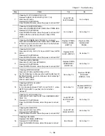
2
Checking SENSOR REGI (1)
Connect the connector J241 of HARNESS ASSY
TRAY1 to SENSOR REGI, with 150 FEEDER ASSY
removed.
Remove EP CARTRIDGE.
Close COVER OPEN (PL1.1.2).
Does the number of Sensor/Switch Check increase by
one, by moving ACTUATOR B with a mini screwdriver?
Check using Chapter 2 Diagnostic [Sensor/Switch
Check].
Replace HVPS/
MCU.
(RRP12.19)
Go to step 4.
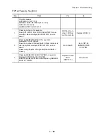
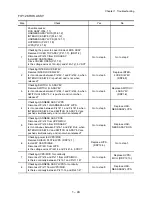
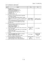
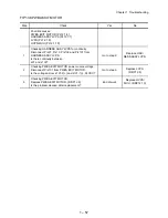
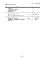
3
Check SENSOR REGI (2)
Connect the connector J241 of HARNESS ASSY
TRAY1 to SENSOR REGI, with 150 FEEDER ASSY
removed.
Remove EP CARTRIDGE.
Close COVER OPEN (PL1.1.2).
Is the voltage across P/J24-11(+) and P/J24-10(-), 3.3
VDC when ACTUATOR B is pushed, and 0 VDC when
released?
Measure the voltage by moving ACTUATOR B with a
mini screwdriver.
Replace HVPS/
MCU.
(RRP12.19)
Go to step 4.
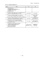
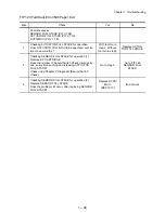
4
Checking the power to SENSOR REGI
Remove EP CARTRIDGE.
Is the voltage across P/J24-9(+) and P/J24-10(-) on
HVPS/ MCU, about 3.3 VDC?
Go to step 5.
Go to step 7.
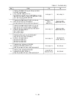
5
Checking HARNESS ASSY CHUTE for continuity
Disconnect P/J24 from HVPS/MCU.
Disconnect P/J245.
Is there continuity between
J24-9 and J245-10?
J24-10 and J245-9?
J24-11 and J245-8?
Go to step 6.
Replace HAR-
NESS ASSY
CHUTE.
Содержание 9045N
Страница 1: ...Laser Printer TallyGenicom 9045N Service Manual J20006AA ...
Страница 16: ...xv Blank Page ...
Страница 20: ...Chapter 1 Troubleshooting Chapter 1 Troubleshooting CONTENTS Blank Page ...
Страница 88: ...1 68 Chapter 1 Troubleshooting Blank Page ...
Страница 160: ...1 140 Chapter 1 Troubleshooting Blank Page ...
Страница 162: ...1 142 Chapter 1 Troubleshooting Blank Page ...
Страница 164: ...Chapter 2 Printer Diagnostics Chapter 2 Diagnostics CONTENTS 11 Print Summary 2 16 ...
Страница 194: ...1 10 Chapter 3 Removal and Replacement Procedures RRPs RRP2 150 PAPER CASSETTE ...
Страница 213: ...1 29 Chapter 3 Removal and Replacement Procedures RRPs RRP3 550 PAPER CASSETTE ...
Страница 240: ...1 56 Chapter 3 Removal and Replacement Procedures RRPs RRP4 150 paper Feeder ...
Страница 257: ...1 73 Chapter 3 Removal and Replacement Procedures RRPs RRP5 550 Paper Feeder ...
Страница 277: ...1 93 Chapter 3 Removal and Replacement Procedures RRPs RRP6 Xerographics ...
Страница 302: ...1 118 Chapter 3 Removal and Replacement Procedures RRPs RRP7 500 Paper Exit ...
Страница 322: ...1 138 Chapter 3 Removal and Replacement Procedures RRPs RRP8 Frame Drive ...
Страница 331: ...1 147 Chapter 3 Removal and Replacement Procedures RRPs RRP9 Electrical ...
Страница 394: ...1 210 Chapter 3 Removal and Replacement Procedures RRPs ...
Страница 403: ...1 219 Chapter 3 Removal and Replacement Procedures RRPs 4 Install the 550 FEEDER OPTION PL 12 2 RRP12 1 ...
Страница 454: ...1 270 Chapter 3 Removal and Replacement Procedures RRPs Blank Page ...
Страница 456: ...Chapter 4 Plug Jack P J Connector Locations Chapter 4 Plug Jack P J Connector Locations CONTENTS Blank Page ...
Страница 459: ...4 3 Chapter 4 Plug Jack P J Connector Locations Blank Page ...
Страница 465: ...4 9 Chapter 4 Plug Jack P J Connector Locations 3 2 OCT Option P J Diagram ...
Страница 468: ...4 12 Chapter 4 Plug Jack P J Connector Locations Blank Page ...
Страница 470: ...Chapter 5 Parts Lists Chapter 5 Parts Lists CONTENTS Blank Page ...
Страница 472: ...5 2 Chapter 5 Parts List PL 1 1 COVER ILLUSTRATION 2 Ref PL10 1 1 7 8 9 9 13 14 15 3 4 6 5 J25014AA 10 16 J244 ...
Страница 479: ...5 9 Chapter 5 Parts List Blank Page ...
Страница 483: ...5 13 Chapter 5 Parts List Blank Page ...
Страница 490: ...5 20 Chapter 5 Parts List PL 7 2 500 PAPER EXIT 2 2 OPTION FACE UP TRAY ILLUSTRA TION ...
Страница 496: ...5 26 Chapter 5 Parts List OPTIONS PL 10 1 OPTION DUPLEX ILLUSTRATION ...
Страница 501: ...5 31 Chapter 5 Parts List Blank Page ...
Страница 529: ...6 19 Chapter 6 Principles of Operation J26119AA EP CARTRIDGE BTR ASSY ...
Страница 531: ...6 21 Chapter 6 Principles of Operation LD Assembly JG6121AA SOS PWB Scanner Assembly ...
Страница 535: ...6 25 Chapter 6 Principles of Operation ...
Страница 547: ...6 37 Chapter 6 Principles of Operation J26615AA PWBA DUPLEX SWITCH DUPLEX SENSOR DUP MOTOR DUPLEX ROLL DUP FAN DUPLEX ...
Страница 558: ...6 48 Chapter 6 Principles of Operation Blank Page ...
Страница 560: ...Chapter 7 Wiring Diagrams and Signal Information Chapter 7 Wiring Diagrams and Signal Information CONTENTS Blank Page ...
Страница 584: ...7 24 Chapter 7 Wiring Diagrams and Signal Information Blank Page ...
Страница 608: ...Chapter 9 ESS Options Chapter 9 Controller ESS Options Contents Blank Page ...
Страница 616: ...9 8 Chapter 9 ESS Options Blank Page ...


