
6 – 22
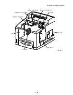
Chapter 6 Principles of Operation
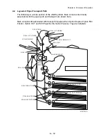
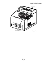
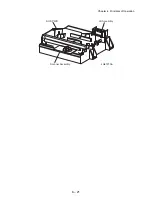
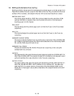
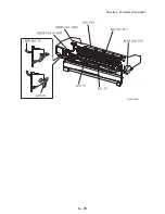
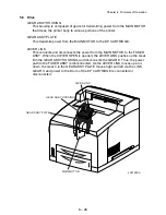
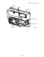
5.4 Fuser
Heat Roll
This is a hollow metal tube having a coated surface. This tube is heated by the
inside Heater Rod. Heat is applied to the paper passing between this roll and the
Pressure Roll. This heat fuses and fixes the toner on the paper.
Pressure Roll
This is a metal shaft coated with sponge rubber. Pressure is applied to the paper
between this roll and the Heat Roll. This pressure presses the melted toner against
the paper.
Heater Assembly
The Heater Assembly consists of a Heater Rod located in a Heat Roll and a
harness connecting the Heater Rod to a terminal. The Heater Rod consists of
heater coil inside a quartz glass and heats up the Heat Roll.
Temperature Sensor
This is a resistor (thermistor) having a known value of resistance that sensitively
varies with temperature. This sensor is mounted in contact with the surface of the
Heat Roll, and monitors the temperature of the surface. The power supply of the
Heater Rod is turned ON and OFF using the signal from this sensor, so that the
surface temperature of the Heat Roll can be maintained within a specified range.
This signal is also used to provide a first stage of overheat protection.
Thermostat Sensor (STS)
Two STS are installed. The STS are connected to the Heat Roll in series.
This provides a second stage of overheat protection. If the first stage does not
prevent the Fuser from overheating, the Thermostat cuts off the power-supply
circuit for the Heater Rod. The STS operates as follows:
(1) If the paper is set incorrectly, the Pressure Roll may melt and adhere. As a countermeasure
against this, the power-supply circuit is cut off to cool down the roll, if the detected temperature
gets higher than a preset temperature.
(2) If the temperatures increase at both sides of the Heat Roll, both ends of the paper may curl.
As a countermeasure against this, the mode is switched to Short lamp lighting to control the tem-
perature rise, if the detected temperature exceeds the preset temperature.
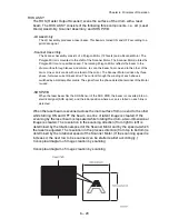
Heat Roll Fingers
These fingers peel off the leading edge of the paper from the Heat Roll to prevent
the paper from getting wound around the Heat Roll.
Heat Roll Diode
The negative charge accumulated on the Heat Roll may deteriorate the toner image
on the paper during fixing. The Heat Roll Diode discharges the charge to the frame
ground.
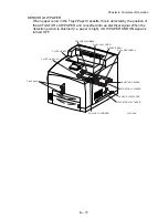
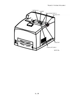
Exit Sensor
This sensor detects the arrival of the paper at a detection point in the exit area
positioned behind the Fuser. This sensor also detects the discharge of the paper
from this point. When the sensor receives light (i.e., paper is present), /EXIT goes
Low.
Содержание 9045N
Страница 1: ...Laser Printer TallyGenicom 9045N Service Manual J20006AA ...
Страница 16: ...xv Blank Page ...
Страница 20: ...Chapter 1 Troubleshooting Chapter 1 Troubleshooting CONTENTS Blank Page ...
Страница 88: ...1 68 Chapter 1 Troubleshooting Blank Page ...
Страница 160: ...1 140 Chapter 1 Troubleshooting Blank Page ...
Страница 162: ...1 142 Chapter 1 Troubleshooting Blank Page ...
Страница 164: ...Chapter 2 Printer Diagnostics Chapter 2 Diagnostics CONTENTS 11 Print Summary 2 16 ...
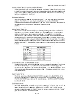
Страница 194: ...1 10 Chapter 3 Removal and Replacement Procedures RRPs RRP2 150 PAPER CASSETTE ...
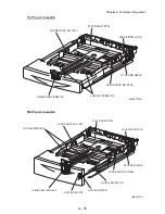
Страница 213: ...1 29 Chapter 3 Removal and Replacement Procedures RRPs RRP3 550 PAPER CASSETTE ...
Страница 240: ...1 56 Chapter 3 Removal and Replacement Procedures RRPs RRP4 150 paper Feeder ...
Страница 257: ...1 73 Chapter 3 Removal and Replacement Procedures RRPs RRP5 550 Paper Feeder ...
Страница 277: ...1 93 Chapter 3 Removal and Replacement Procedures RRPs RRP6 Xerographics ...
Страница 302: ...1 118 Chapter 3 Removal and Replacement Procedures RRPs RRP7 500 Paper Exit ...
Страница 322: ...1 138 Chapter 3 Removal and Replacement Procedures RRPs RRP8 Frame Drive ...
Страница 331: ...1 147 Chapter 3 Removal and Replacement Procedures RRPs RRP9 Electrical ...
Страница 394: ...1 210 Chapter 3 Removal and Replacement Procedures RRPs ...
Страница 403: ...1 219 Chapter 3 Removal and Replacement Procedures RRPs 4 Install the 550 FEEDER OPTION PL 12 2 RRP12 1 ...
Страница 454: ...1 270 Chapter 3 Removal and Replacement Procedures RRPs Blank Page ...
Страница 456: ...Chapter 4 Plug Jack P J Connector Locations Chapter 4 Plug Jack P J Connector Locations CONTENTS Blank Page ...
Страница 459: ...4 3 Chapter 4 Plug Jack P J Connector Locations Blank Page ...
Страница 465: ...4 9 Chapter 4 Plug Jack P J Connector Locations 3 2 OCT Option P J Diagram ...
Страница 468: ...4 12 Chapter 4 Plug Jack P J Connector Locations Blank Page ...
Страница 470: ...Chapter 5 Parts Lists Chapter 5 Parts Lists CONTENTS Blank Page ...
Страница 472: ...5 2 Chapter 5 Parts List PL 1 1 COVER ILLUSTRATION 2 Ref PL10 1 1 7 8 9 9 13 14 15 3 4 6 5 J25014AA 10 16 J244 ...
Страница 479: ...5 9 Chapter 5 Parts List Blank Page ...
Страница 483: ...5 13 Chapter 5 Parts List Blank Page ...
Страница 490: ...5 20 Chapter 5 Parts List PL 7 2 500 PAPER EXIT 2 2 OPTION FACE UP TRAY ILLUSTRA TION ...
Страница 496: ...5 26 Chapter 5 Parts List OPTIONS PL 10 1 OPTION DUPLEX ILLUSTRATION ...
Страница 501: ...5 31 Chapter 5 Parts List Blank Page ...
Страница 529: ...6 19 Chapter 6 Principles of Operation J26119AA EP CARTRIDGE BTR ASSY ...
Страница 531: ...6 21 Chapter 6 Principles of Operation LD Assembly JG6121AA SOS PWB Scanner Assembly ...
Страница 535: ...6 25 Chapter 6 Principles of Operation ...
Страница 547: ...6 37 Chapter 6 Principles of Operation J26615AA PWBA DUPLEX SWITCH DUPLEX SENSOR DUP MOTOR DUPLEX ROLL DUP FAN DUPLEX ...
Страница 558: ...6 48 Chapter 6 Principles of Operation Blank Page ...
Страница 560: ...Chapter 7 Wiring Diagrams and Signal Information Chapter 7 Wiring Diagrams and Signal Information CONTENTS Blank Page ...
Страница 584: ...7 24 Chapter 7 Wiring Diagrams and Signal Information Blank Page ...
Страница 608: ...Chapter 9 ESS Options Chapter 9 Controller ESS Options Contents Blank Page ...
Страница 616: ...9 8 Chapter 9 ESS Options Blank Page ...


