
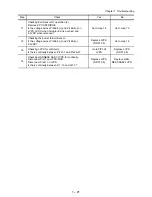

1 – 14
Chapter 1 Troubleshooting
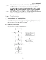
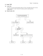
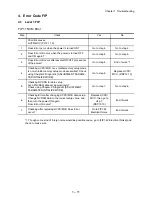
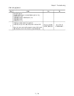
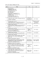
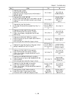
FIP1.4 Fan Error
Step Check
Yes
No
Possible causes:
FAN MAIN (PL1.1.14)
FAN SUB (PL8.1.5)
LVPS (PL12.1.5)
HVPS/MCU (PL12.1.19)
1
Checking FAN MAIN for rotation (1).
Does FAN MAIN rotate, when the power is turned ON?
Go to step 2.
Go to step 5.
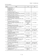
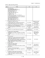
2
Checking FAN SUB for rotation (1).
Does FAN SUB rotate, when the power is turned ON?
Go to step 3.
Go to step 9.
3
Checking FAN MAIN for rotation (2).
Does FAN MAIN rotate in high-speed?
Check using Chapter 2 Diagnostic [Fan Motor, High
Speed Test].
Go to step 4.
Go to step 5.
4
Checking FAN SUB for rotation (2).
Does FAN SUB rotate in high-speed?
Check using Chapter 2 Diagnostic [Fan Motor, High
Speed Test].
Replace HVPS/
MCU, and watch
FUN SUB for a
while.
(RRP12.10)
Go to step 9.
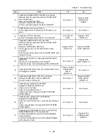
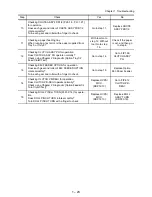
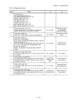
5
Checking the power to FAN MAIN.
Is FAN MAIN connected correctly, and is the voltage
across P/J24-18(+) and P/J24-17(-), 24 VDC?
(12 VDC, when half-speed)?
Go to step 6.
Go to step 7.
6
Checking the FAN ALARM signal (1).
Is the voltage across P/J24-17(+) and P/J24-16(-), 0.82
VDC or more?
Replace FAN
MAIN. (RRP12.6)
Replace HVPS/
MCU. (RRP12.10)
7
Checking after replacing FAN MAIN
Replace the FAN MAIN.
Does FAN Error occur when the power is turned ON?
Go to step 8.
End of work
8
Checking after replacing LVPS
Replace the LVPS.
Does FAN Error occur when the power is turned ON?
Replace HVPS/
MCU.
(RRP12.10)
End of work
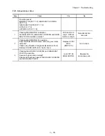
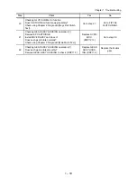
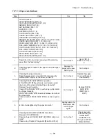
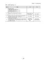
9
Checking the power to FAN SUB
Is FAN SUB connected correctly, and is the voltage
across P/J27-19(+) and P/J27-18(-), 24 VDC?
(12 VDC, when half-speed)?
Go to step 10.
Go to step 11.
10
Checking the FAN ALARM signal
Is the voltage across P/J27-18(+) and P/J27-17(-), 0.82
VDC or more?
Replace FAN
SUB (RRP8.2)
Replace HVPS/
MCU. (RRP12.10)
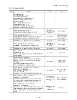
11
Checking after replacing FAN SUB
Replace the FAN SUB.
Does FAN Error occur when the power is turned ON?
Go to step 12.
End of work
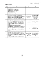
12
Checking after replacing LVPS
Replace the LVPS.
Does FAN Error occur when the power is turned ON?
Replace HVPS/
MCU.
(RRP12.10)
End of work
Содержание 9045N
Страница 1: ...Laser Printer TallyGenicom 9045N Service Manual J20006AA ...
Страница 16: ...xv Blank Page ...
Страница 20: ...Chapter 1 Troubleshooting Chapter 1 Troubleshooting CONTENTS Blank Page ...
Страница 88: ...1 68 Chapter 1 Troubleshooting Blank Page ...
Страница 160: ...1 140 Chapter 1 Troubleshooting Blank Page ...
Страница 162: ...1 142 Chapter 1 Troubleshooting Blank Page ...
Страница 164: ...Chapter 2 Printer Diagnostics Chapter 2 Diagnostics CONTENTS 11 Print Summary 2 16 ...
Страница 194: ...1 10 Chapter 3 Removal and Replacement Procedures RRPs RRP2 150 PAPER CASSETTE ...
Страница 213: ...1 29 Chapter 3 Removal and Replacement Procedures RRPs RRP3 550 PAPER CASSETTE ...
Страница 240: ...1 56 Chapter 3 Removal and Replacement Procedures RRPs RRP4 150 paper Feeder ...
Страница 257: ...1 73 Chapter 3 Removal and Replacement Procedures RRPs RRP5 550 Paper Feeder ...
Страница 277: ...1 93 Chapter 3 Removal and Replacement Procedures RRPs RRP6 Xerographics ...
Страница 302: ...1 118 Chapter 3 Removal and Replacement Procedures RRPs RRP7 500 Paper Exit ...
Страница 322: ...1 138 Chapter 3 Removal and Replacement Procedures RRPs RRP8 Frame Drive ...
Страница 331: ...1 147 Chapter 3 Removal and Replacement Procedures RRPs RRP9 Electrical ...
Страница 394: ...1 210 Chapter 3 Removal and Replacement Procedures RRPs ...
Страница 403: ...1 219 Chapter 3 Removal and Replacement Procedures RRPs 4 Install the 550 FEEDER OPTION PL 12 2 RRP12 1 ...
Страница 454: ...1 270 Chapter 3 Removal and Replacement Procedures RRPs Blank Page ...
Страница 456: ...Chapter 4 Plug Jack P J Connector Locations Chapter 4 Plug Jack P J Connector Locations CONTENTS Blank Page ...
Страница 459: ...4 3 Chapter 4 Plug Jack P J Connector Locations Blank Page ...
Страница 465: ...4 9 Chapter 4 Plug Jack P J Connector Locations 3 2 OCT Option P J Diagram ...
Страница 468: ...4 12 Chapter 4 Plug Jack P J Connector Locations Blank Page ...
Страница 470: ...Chapter 5 Parts Lists Chapter 5 Parts Lists CONTENTS Blank Page ...
Страница 472: ...5 2 Chapter 5 Parts List PL 1 1 COVER ILLUSTRATION 2 Ref PL10 1 1 7 8 9 9 13 14 15 3 4 6 5 J25014AA 10 16 J244 ...
Страница 479: ...5 9 Chapter 5 Parts List Blank Page ...
Страница 483: ...5 13 Chapter 5 Parts List Blank Page ...
Страница 490: ...5 20 Chapter 5 Parts List PL 7 2 500 PAPER EXIT 2 2 OPTION FACE UP TRAY ILLUSTRA TION ...
Страница 496: ...5 26 Chapter 5 Parts List OPTIONS PL 10 1 OPTION DUPLEX ILLUSTRATION ...
Страница 501: ...5 31 Chapter 5 Parts List Blank Page ...
Страница 529: ...6 19 Chapter 6 Principles of Operation J26119AA EP CARTRIDGE BTR ASSY ...
Страница 531: ...6 21 Chapter 6 Principles of Operation LD Assembly JG6121AA SOS PWB Scanner Assembly ...
Страница 535: ...6 25 Chapter 6 Principles of Operation ...
Страница 547: ...6 37 Chapter 6 Principles of Operation J26615AA PWBA DUPLEX SWITCH DUPLEX SENSOR DUP MOTOR DUPLEX ROLL DUP FAN DUPLEX ...
Страница 558: ...6 48 Chapter 6 Principles of Operation Blank Page ...
Страница 560: ...Chapter 7 Wiring Diagrams and Signal Information Chapter 7 Wiring Diagrams and Signal Information CONTENTS Blank Page ...
Страница 584: ...7 24 Chapter 7 Wiring Diagrams and Signal Information Blank Page ...
Страница 608: ...Chapter 9 ESS Options Chapter 9 Controller ESS Options Contents Blank Page ...
Страница 616: ...9 8 Chapter 9 ESS Options Blank Page ...


