


6 – 41
Chapter 6 Principles of Operation
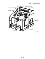
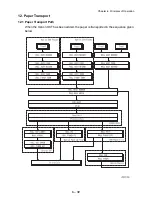
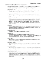
13. Actions of Main Functional Components
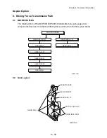
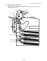
The Option OCT is available as an optional unit for JIGEN laser printer. Offset output
is enabled by mounting this optional unit to the top of the 500 Paper Exit.
MOTOR ASSY OCT
This motor gives the driving force to the ROLL OCT LOWER and ROLL OCT
UPPER, which transport the printed paper to the tray of the OCT.
MOTOR ASSY OFFSET
This motor gives the driving force to the CHUTE OFFSET ASSY via the GEAR
CAM.
SOLENOID ASSY GATE
This solenoid switches between the paper paths to the standard and OCT paper
output trays. When the SOLENOID ASSY GATE operates, the GATE OCT EXIT is
operated by the LINK GATE OCT pushed downward against the spindle of the
SOLENOID ASSY GATE. Thus, the paper output direction is switched to the OCT
paper output tray.
PWBA OCT
A CPU is installed in the PWBA OCT. This CPU receives instructions from HVPS/
MCU and information from sensors and switches, and controls the operation for
transporting the paper through the OCT.
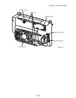
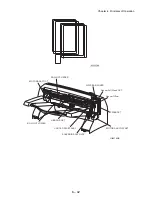
S/W REAR COVER
This switch detects that the COVER REAR is closed.
SENSOR OCT
This sensor detects the presence or absence of paper in the OCT.
Sensor Full Stack OCT This sensor is located on the PWBA OCT, and detects that
the paper output tray is full, using the ACTUATOR FULL STACK.
Sensor Offset
This sensor is located on the PWBA OCT, and detects an offset operation, using
the Actuator in the CHUTE OFFSET.
ROLL OCT LOWER
This roll transports the printed paper sent out from the Fuser, to the ROLL UPPER
OCT.
ROLL OCT UPPER
This roll discharges the printed paper sent out from the ROLL OCT LOWER, to the
tray of the OCT.
CHUTE OFFSET ASSY
This is driven by the MOTOR ASSY OCT and GEAR CAM. During paper output, it
moves right and left to perform offset operation. The standard distance between
offset paper and non-offset paper is 25mm. The Offset Deal (the closest distance
between a batch of offset sheets and a batch of non-offset sheets) should be more
than 10mm.
Содержание 9045N
Страница 1: ...Laser Printer TallyGenicom 9045N Service Manual J20006AA ...
Страница 16: ...xv Blank Page ...
Страница 20: ...Chapter 1 Troubleshooting Chapter 1 Troubleshooting CONTENTS Blank Page ...
Страница 88: ...1 68 Chapter 1 Troubleshooting Blank Page ...
Страница 160: ...1 140 Chapter 1 Troubleshooting Blank Page ...
Страница 162: ...1 142 Chapter 1 Troubleshooting Blank Page ...
Страница 164: ...Chapter 2 Printer Diagnostics Chapter 2 Diagnostics CONTENTS 11 Print Summary 2 16 ...
Страница 194: ...1 10 Chapter 3 Removal and Replacement Procedures RRPs RRP2 150 PAPER CASSETTE ...
Страница 213: ...1 29 Chapter 3 Removal and Replacement Procedures RRPs RRP3 550 PAPER CASSETTE ...
Страница 240: ...1 56 Chapter 3 Removal and Replacement Procedures RRPs RRP4 150 paper Feeder ...
Страница 257: ...1 73 Chapter 3 Removal and Replacement Procedures RRPs RRP5 550 Paper Feeder ...
Страница 277: ...1 93 Chapter 3 Removal and Replacement Procedures RRPs RRP6 Xerographics ...
Страница 302: ...1 118 Chapter 3 Removal and Replacement Procedures RRPs RRP7 500 Paper Exit ...
Страница 322: ...1 138 Chapter 3 Removal and Replacement Procedures RRPs RRP8 Frame Drive ...
Страница 331: ...1 147 Chapter 3 Removal and Replacement Procedures RRPs RRP9 Electrical ...
Страница 394: ...1 210 Chapter 3 Removal and Replacement Procedures RRPs ...
Страница 403: ...1 219 Chapter 3 Removal and Replacement Procedures RRPs 4 Install the 550 FEEDER OPTION PL 12 2 RRP12 1 ...
Страница 454: ...1 270 Chapter 3 Removal and Replacement Procedures RRPs Blank Page ...
Страница 456: ...Chapter 4 Plug Jack P J Connector Locations Chapter 4 Plug Jack P J Connector Locations CONTENTS Blank Page ...
Страница 459: ...4 3 Chapter 4 Plug Jack P J Connector Locations Blank Page ...
Страница 465: ...4 9 Chapter 4 Plug Jack P J Connector Locations 3 2 OCT Option P J Diagram ...
Страница 468: ...4 12 Chapter 4 Plug Jack P J Connector Locations Blank Page ...
Страница 470: ...Chapter 5 Parts Lists Chapter 5 Parts Lists CONTENTS Blank Page ...
Страница 472: ...5 2 Chapter 5 Parts List PL 1 1 COVER ILLUSTRATION 2 Ref PL10 1 1 7 8 9 9 13 14 15 3 4 6 5 J25014AA 10 16 J244 ...
Страница 479: ...5 9 Chapter 5 Parts List Blank Page ...
Страница 483: ...5 13 Chapter 5 Parts List Blank Page ...
Страница 490: ...5 20 Chapter 5 Parts List PL 7 2 500 PAPER EXIT 2 2 OPTION FACE UP TRAY ILLUSTRA TION ...
Страница 496: ...5 26 Chapter 5 Parts List OPTIONS PL 10 1 OPTION DUPLEX ILLUSTRATION ...
Страница 501: ...5 31 Chapter 5 Parts List Blank Page ...
Страница 529: ...6 19 Chapter 6 Principles of Operation J26119AA EP CARTRIDGE BTR ASSY ...
Страница 531: ...6 21 Chapter 6 Principles of Operation LD Assembly JG6121AA SOS PWB Scanner Assembly ...
Страница 535: ...6 25 Chapter 6 Principles of Operation ...
Страница 547: ...6 37 Chapter 6 Principles of Operation J26615AA PWBA DUPLEX SWITCH DUPLEX SENSOR DUP MOTOR DUPLEX ROLL DUP FAN DUPLEX ...
Страница 558: ...6 48 Chapter 6 Principles of Operation Blank Page ...
Страница 560: ...Chapter 7 Wiring Diagrams and Signal Information Chapter 7 Wiring Diagrams and Signal Information CONTENTS Blank Page ...
Страница 584: ...7 24 Chapter 7 Wiring Diagrams and Signal Information Blank Page ...
Страница 608: ...Chapter 9 ESS Options Chapter 9 Controller ESS Options Contents Blank Page ...
Страница 616: ...9 8 Chapter 9 ESS Options Blank Page ...


