


1 - 245
Chapter 3 Removal and Replacement Procedures (RRPs)
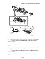
When installing the RACK SIZE, be sure to draw out the GUIDE ASSY END 550 (PL
12.3.43) as far as it will go.(NOTE 1).
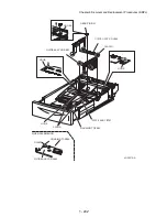
3)
Install the COVER EXTENSION (PL 12.3.31) to the HOUSING EXTENSION 550 using the 4
screws (gold tapping, 6mm).
When installing, make sure the COVER EXTENSION is inserted under 3 claws of the
HOUSING EXTENSION 550.(NOTE2).
Use 6mm size of fixed screw. If 8mm size of screw is used, HOUSING EXTENSION 550
doesn't operate smoothly and LOCK EXTENSION 550 doesn't operate correctly.
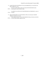
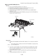
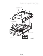
4)
Install the HOUSING EXTENSION 550 and HOUSING TOP 550 (PL 12.3.16) to the HOUSING
BASE 550 while pushing the LINK SW SIZE1-550 (PL 12.3.45), LINK SW SIZE2-550 (PL
12.3.46) and LINK SW SIZE3-550 (PL 12.3.47) of the HOUSING BASE 550 outward as shown
in the figure.
Be sure to put 2 claws at the tip of the PLATE ASSY BTM under the hooks on the HOUS-
ING TOP 550.(NOTE3).
5)
After assembling the HOUSING TOP 550 with HOUSING BASE 550 using the 4 hooks, secure
them using the 2 screws (gold tapping, 8mm) from both right and left sides, as well as the 6
screws (gold tapping, 8mm) on back.
After tightening the screws, move the GUIDE ASSY END 550 back and forth, and make
sure that the LINK SW SIZEs operate smoothly.
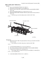
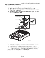
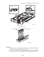
6)
Insert the link lever of the GUIDE INDICATOR1 (PL 12.3.34) into the hole of the PLATE ASSY
BTM. (Figure 20.21)
7)
While pressing down the hook of the HOUSING TOP 550, install the GUIDE ASSY SD R550
(PL 12.3.13) to the HOUSING TOP 550.(NOTE4).
After installing, make sure that the 3 claws of the GUIDE ASSY SD R550 sit correctly in
the grooves of the HOUSING TOP 550.
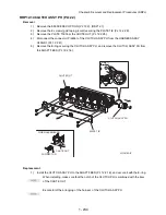
8)
While pressing down the hook of the HOUSING TOP 550, install the GUIDE ASSY SD L550
(PL 12.3.11) to the HOUSING TOP 550.
After installing, make sure that the 3 claws of the GUIDE ASSY SD L550 sit correctly in
the grooves of the HOUSING TOP 550.(NOTE4).
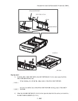
9)
Push the PLATE ASSY BTM downward to lock.
10) With completely opened GUIDE ASSY SD L550 and GUIDE ASSY SD R550 to the both sides,
Install the GEAR PINION (PL 12.3.12) to the HOUSING TOP 550.
When installing the GEAR PINION, make sure the GUIDE ASSY SD R550 and GUIDE
ASSY SD L550 are completely opened. If not, the side register may be misaligned.
11) Install the COVER CST (PL 12.3.1) to the 550 PAPER CASSETTE.
Содержание 9045N
Страница 1: ...Laser Printer TallyGenicom 9045N Service Manual J20006AA ...
Страница 16: ...xv Blank Page ...
Страница 20: ...Chapter 1 Troubleshooting Chapter 1 Troubleshooting CONTENTS Blank Page ...
Страница 88: ...1 68 Chapter 1 Troubleshooting Blank Page ...
Страница 160: ...1 140 Chapter 1 Troubleshooting Blank Page ...
Страница 162: ...1 142 Chapter 1 Troubleshooting Blank Page ...
Страница 164: ...Chapter 2 Printer Diagnostics Chapter 2 Diagnostics CONTENTS 11 Print Summary 2 16 ...
Страница 194: ...1 10 Chapter 3 Removal and Replacement Procedures RRPs RRP2 150 PAPER CASSETTE ...
Страница 213: ...1 29 Chapter 3 Removal and Replacement Procedures RRPs RRP3 550 PAPER CASSETTE ...
Страница 240: ...1 56 Chapter 3 Removal and Replacement Procedures RRPs RRP4 150 paper Feeder ...
Страница 257: ...1 73 Chapter 3 Removal and Replacement Procedures RRPs RRP5 550 Paper Feeder ...
Страница 277: ...1 93 Chapter 3 Removal and Replacement Procedures RRPs RRP6 Xerographics ...
Страница 302: ...1 118 Chapter 3 Removal and Replacement Procedures RRPs RRP7 500 Paper Exit ...
Страница 322: ...1 138 Chapter 3 Removal and Replacement Procedures RRPs RRP8 Frame Drive ...
Страница 331: ...1 147 Chapter 3 Removal and Replacement Procedures RRPs RRP9 Electrical ...
Страница 394: ...1 210 Chapter 3 Removal and Replacement Procedures RRPs ...
Страница 403: ...1 219 Chapter 3 Removal and Replacement Procedures RRPs 4 Install the 550 FEEDER OPTION PL 12 2 RRP12 1 ...
Страница 454: ...1 270 Chapter 3 Removal and Replacement Procedures RRPs Blank Page ...
Страница 456: ...Chapter 4 Plug Jack P J Connector Locations Chapter 4 Plug Jack P J Connector Locations CONTENTS Blank Page ...
Страница 459: ...4 3 Chapter 4 Plug Jack P J Connector Locations Blank Page ...
Страница 465: ...4 9 Chapter 4 Plug Jack P J Connector Locations 3 2 OCT Option P J Diagram ...
Страница 468: ...4 12 Chapter 4 Plug Jack P J Connector Locations Blank Page ...
Страница 470: ...Chapter 5 Parts Lists Chapter 5 Parts Lists CONTENTS Blank Page ...
Страница 472: ...5 2 Chapter 5 Parts List PL 1 1 COVER ILLUSTRATION 2 Ref PL10 1 1 7 8 9 9 13 14 15 3 4 6 5 J25014AA 10 16 J244 ...
Страница 479: ...5 9 Chapter 5 Parts List Blank Page ...
Страница 483: ...5 13 Chapter 5 Parts List Blank Page ...
Страница 490: ...5 20 Chapter 5 Parts List PL 7 2 500 PAPER EXIT 2 2 OPTION FACE UP TRAY ILLUSTRA TION ...
Страница 496: ...5 26 Chapter 5 Parts List OPTIONS PL 10 1 OPTION DUPLEX ILLUSTRATION ...
Страница 501: ...5 31 Chapter 5 Parts List Blank Page ...
Страница 529: ...6 19 Chapter 6 Principles of Operation J26119AA EP CARTRIDGE BTR ASSY ...
Страница 531: ...6 21 Chapter 6 Principles of Operation LD Assembly JG6121AA SOS PWB Scanner Assembly ...
Страница 535: ...6 25 Chapter 6 Principles of Operation ...
Страница 547: ...6 37 Chapter 6 Principles of Operation J26615AA PWBA DUPLEX SWITCH DUPLEX SENSOR DUP MOTOR DUPLEX ROLL DUP FAN DUPLEX ...
Страница 558: ...6 48 Chapter 6 Principles of Operation Blank Page ...
Страница 560: ...Chapter 7 Wiring Diagrams and Signal Information Chapter 7 Wiring Diagrams and Signal Information CONTENTS Blank Page ...
Страница 584: ...7 24 Chapter 7 Wiring Diagrams and Signal Information Blank Page ...
Страница 608: ...Chapter 9 ESS Options Chapter 9 Controller ESS Options Contents Blank Page ...
Страница 616: ...9 8 Chapter 9 ESS Options Blank Page ...


