


1 - 27
Chapter 3 Removal and Replacement Procedures (RRPs)
Replacement
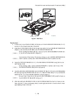
When installing, be sure to lift up the PLATE ASSEMBLY BTM. If the PLATE ASSEMBLY
BTM is inclined, a paper skew or jam may occur. Check after the installation is completed.
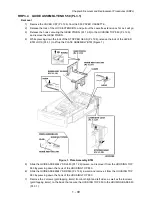
1)
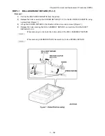
Put the SPRING STOPPER GEAR (PL 2.1) into the STOPPER GEAR (PL 2.1), and secure the
STOPPER GEAR to the HOUSING BASE 150 (PL 2.1) using the 2 screws (gold tapping, 6mm).
When installing the STOPPER GEAR, be careful not to lose the SPRING STOPPER
GEAR.
Install the STOPPER GEAR so that one end of the SPRING STOPPER GEAR is in con-
tact with the plate located on the back of the HOUSING BASE 150 as shown (NOTE 2)
(Figure 1)
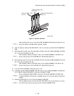
2)
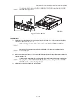
Install the GEAR LEVER LOCK (PL 2.1.25) to the HOUSING BASE 150.
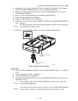
3)
Install the SPRING BTM LOCK (PL 2.1) to the projection of the RACK BTM LOCK 150 (PL 2.1),
and install them to the HOUSING BASE 150.
When installing the RACK BTM LOCK150, be sure to install it with the LEVER BTM
LOCK lifted up. After installing, push down the LEVER BTM LOCK and then release,
check that the projection of the LEVER BTM LOCK hits the stopper of the
HOUSING BASE 150 and the triangle mark is placed above the stopper.
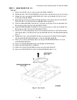
4)
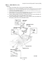
Install the GEAR BTM LOCK PINION (PL 2.1) to the HOUSING BASE 150, and engage the gear.
5)
Secure the COVER BTM UP 150 (PL 2.1) to the HOUSING BASE 150 using the screw (gold tap-
ping, 6mm).
6)
Install the GEAR PB R (PL 2.1) to the SHAFT PB (PL 2.1), and secure it with the hook.
Be sure to install the hook of the GEAR PB R into the groove of the SHAFT PB.
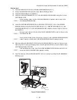
7)
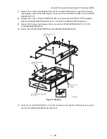
Install the PLATE GEAR LOCK 150 (PL 2.1) to the HOUSING BASE 150, and secure it with the
hook.
8)
Secure the PLATE GEAR LOCK 150 using the screw (gold tapping, 8mm).
9)
Push the PLATE ASSEMBLY BTM (PL 2.1) downward to lock.
Содержание 9045N
Страница 1: ...Laser Printer TallyGenicom 9045N Service Manual J20006AA ...
Страница 16: ...xv Blank Page ...
Страница 20: ...Chapter 1 Troubleshooting Chapter 1 Troubleshooting CONTENTS Blank Page ...
Страница 88: ...1 68 Chapter 1 Troubleshooting Blank Page ...
Страница 160: ...1 140 Chapter 1 Troubleshooting Blank Page ...
Страница 162: ...1 142 Chapter 1 Troubleshooting Blank Page ...
Страница 164: ...Chapter 2 Printer Diagnostics Chapter 2 Diagnostics CONTENTS 11 Print Summary 2 16 ...
Страница 194: ...1 10 Chapter 3 Removal and Replacement Procedures RRPs RRP2 150 PAPER CASSETTE ...
Страница 213: ...1 29 Chapter 3 Removal and Replacement Procedures RRPs RRP3 550 PAPER CASSETTE ...
Страница 240: ...1 56 Chapter 3 Removal and Replacement Procedures RRPs RRP4 150 paper Feeder ...
Страница 257: ...1 73 Chapter 3 Removal and Replacement Procedures RRPs RRP5 550 Paper Feeder ...
Страница 277: ...1 93 Chapter 3 Removal and Replacement Procedures RRPs RRP6 Xerographics ...
Страница 302: ...1 118 Chapter 3 Removal and Replacement Procedures RRPs RRP7 500 Paper Exit ...
Страница 322: ...1 138 Chapter 3 Removal and Replacement Procedures RRPs RRP8 Frame Drive ...
Страница 331: ...1 147 Chapter 3 Removal and Replacement Procedures RRPs RRP9 Electrical ...
Страница 394: ...1 210 Chapter 3 Removal and Replacement Procedures RRPs ...
Страница 403: ...1 219 Chapter 3 Removal and Replacement Procedures RRPs 4 Install the 550 FEEDER OPTION PL 12 2 RRP12 1 ...
Страница 454: ...1 270 Chapter 3 Removal and Replacement Procedures RRPs Blank Page ...
Страница 456: ...Chapter 4 Plug Jack P J Connector Locations Chapter 4 Plug Jack P J Connector Locations CONTENTS Blank Page ...
Страница 459: ...4 3 Chapter 4 Plug Jack P J Connector Locations Blank Page ...
Страница 465: ...4 9 Chapter 4 Plug Jack P J Connector Locations 3 2 OCT Option P J Diagram ...
Страница 468: ...4 12 Chapter 4 Plug Jack P J Connector Locations Blank Page ...
Страница 470: ...Chapter 5 Parts Lists Chapter 5 Parts Lists CONTENTS Blank Page ...
Страница 472: ...5 2 Chapter 5 Parts List PL 1 1 COVER ILLUSTRATION 2 Ref PL10 1 1 7 8 9 9 13 14 15 3 4 6 5 J25014AA 10 16 J244 ...
Страница 479: ...5 9 Chapter 5 Parts List Blank Page ...
Страница 483: ...5 13 Chapter 5 Parts List Blank Page ...
Страница 490: ...5 20 Chapter 5 Parts List PL 7 2 500 PAPER EXIT 2 2 OPTION FACE UP TRAY ILLUSTRA TION ...
Страница 496: ...5 26 Chapter 5 Parts List OPTIONS PL 10 1 OPTION DUPLEX ILLUSTRATION ...
Страница 501: ...5 31 Chapter 5 Parts List Blank Page ...
Страница 529: ...6 19 Chapter 6 Principles of Operation J26119AA EP CARTRIDGE BTR ASSY ...
Страница 531: ...6 21 Chapter 6 Principles of Operation LD Assembly JG6121AA SOS PWB Scanner Assembly ...
Страница 535: ...6 25 Chapter 6 Principles of Operation ...
Страница 547: ...6 37 Chapter 6 Principles of Operation J26615AA PWBA DUPLEX SWITCH DUPLEX SENSOR DUP MOTOR DUPLEX ROLL DUP FAN DUPLEX ...
Страница 558: ...6 48 Chapter 6 Principles of Operation Blank Page ...
Страница 560: ...Chapter 7 Wiring Diagrams and Signal Information Chapter 7 Wiring Diagrams and Signal Information CONTENTS Blank Page ...
Страница 584: ...7 24 Chapter 7 Wiring Diagrams and Signal Information Blank Page ...
Страница 608: ...Chapter 9 ESS Options Chapter 9 Controller ESS Options Contents Blank Page ...
Страница 616: ...9 8 Chapter 9 ESS Options Blank Page ...


