


1 – 45
Chapter 1 Troubleshooting
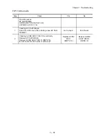
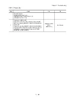
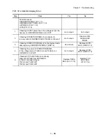
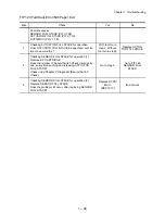
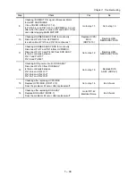
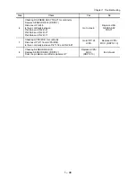
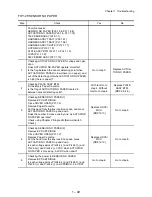
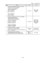
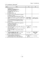
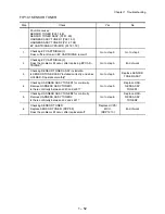
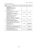
FIP1.27 FUSER ASSY
Step Check
Yes
No
Possible causes:
FUSER ASSY (PL8.1.20)
HVPS/MCU (PL12.1.19)
INTERLOCK S/W 24V (PL8.1.11)
HARNESS ASSY FUSER 100V/200V (PL8.1.17)
HARNESS ASSY AC100V/200V (PL12.1.8)
LVPS (PL12.1.5)
HARNESS ASSY LVPS (PL12.1.1)
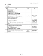
1
Checking Heater circuit for continuity
Remove SHIELD PLATE LVPS. (RRP12.1)
Disconnect P/J47 from LVPS.
Is there continuity between
J47-1 and J47-5?
J47-1 and J47-3?
Go to step 3.
Go to step 2.
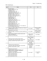
2
Checking HARNESS ASSY FUSER for continuity
Remove FUSER ASSY. (RRP8.8)
Warning; Start the operation after the FUSER ASSY
have cooled down.
Is there continuity between
J4647B-3 and J47-1?
J4647B-2 and J47-3?
J4647B-1 and J47-5?
Replace FUSER
ASSY. (RRP8.8)
Replace HAR-
NESS ASSY
FUSER. (RRP8.7)
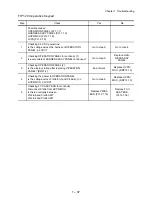
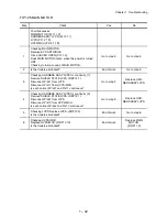
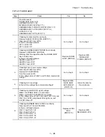
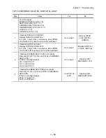
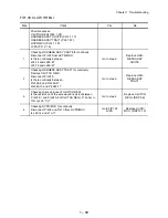
3
Checking Fuser power source voltage
Disconnect P/J48 from LVPS.
Remove EP CARTRIDGE.
Turn the power to ON.
Is the voltage across P/J48-1 and P/J48-3, commercial
voltage?
Go to step 5.
Go to step 4.
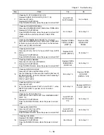
4
Checking AC line voltage
Is the AC line voltage the commercial voltage?
Replace HAR-
NESS ASSY
AC100V/200V
(RRP12.4)
Inform the client or
the electrician.
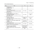
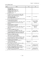
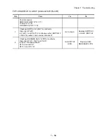
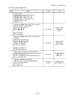
5
Checking Heater Rod ON signal voltage
Make sure FUSER ASSY is cooled down.
Make sure that EP CARTRIDGE is removed.
Is the voltage across P/J41-13(+) and P/J41-12(+) and
P/J41-3(-), 0VDC when Heater Rod lights on, and
3.3VDC when off?
Go to step 7.
Go to step 6.
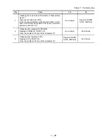
6
Checking HARNESS ASSY LVPS for continuity
Disconnect P/J11 from HVPS/MCU.
Is there continuity between
P/J41-1 and P/J11-16?
P/J41-9 and P/J11-8?
P/J41-10 and P/J11-7?
P/J41-12 and P/J11-5?
P/J41-13 and P/J11-4?
Replace HVPS/
MCU.
(RRP12.10)
Replace HAR-
NESS ASSY LVPS.
Содержание 9045N
Страница 1: ...Laser Printer TallyGenicom 9045N Service Manual J20006AA ...
Страница 16: ...xv Blank Page ...
Страница 20: ...Chapter 1 Troubleshooting Chapter 1 Troubleshooting CONTENTS Blank Page ...
Страница 88: ...1 68 Chapter 1 Troubleshooting Blank Page ...
Страница 160: ...1 140 Chapter 1 Troubleshooting Blank Page ...
Страница 162: ...1 142 Chapter 1 Troubleshooting Blank Page ...
Страница 164: ...Chapter 2 Printer Diagnostics Chapter 2 Diagnostics CONTENTS 11 Print Summary 2 16 ...
Страница 194: ...1 10 Chapter 3 Removal and Replacement Procedures RRPs RRP2 150 PAPER CASSETTE ...
Страница 213: ...1 29 Chapter 3 Removal and Replacement Procedures RRPs RRP3 550 PAPER CASSETTE ...
Страница 240: ...1 56 Chapter 3 Removal and Replacement Procedures RRPs RRP4 150 paper Feeder ...
Страница 257: ...1 73 Chapter 3 Removal and Replacement Procedures RRPs RRP5 550 Paper Feeder ...
Страница 277: ...1 93 Chapter 3 Removal and Replacement Procedures RRPs RRP6 Xerographics ...
Страница 302: ...1 118 Chapter 3 Removal and Replacement Procedures RRPs RRP7 500 Paper Exit ...
Страница 322: ...1 138 Chapter 3 Removal and Replacement Procedures RRPs RRP8 Frame Drive ...
Страница 331: ...1 147 Chapter 3 Removal and Replacement Procedures RRPs RRP9 Electrical ...
Страница 394: ...1 210 Chapter 3 Removal and Replacement Procedures RRPs ...
Страница 403: ...1 219 Chapter 3 Removal and Replacement Procedures RRPs 4 Install the 550 FEEDER OPTION PL 12 2 RRP12 1 ...
Страница 454: ...1 270 Chapter 3 Removal and Replacement Procedures RRPs Blank Page ...
Страница 456: ...Chapter 4 Plug Jack P J Connector Locations Chapter 4 Plug Jack P J Connector Locations CONTENTS Blank Page ...
Страница 459: ...4 3 Chapter 4 Plug Jack P J Connector Locations Blank Page ...
Страница 465: ...4 9 Chapter 4 Plug Jack P J Connector Locations 3 2 OCT Option P J Diagram ...
Страница 468: ...4 12 Chapter 4 Plug Jack P J Connector Locations Blank Page ...
Страница 470: ...Chapter 5 Parts Lists Chapter 5 Parts Lists CONTENTS Blank Page ...
Страница 472: ...5 2 Chapter 5 Parts List PL 1 1 COVER ILLUSTRATION 2 Ref PL10 1 1 7 8 9 9 13 14 15 3 4 6 5 J25014AA 10 16 J244 ...
Страница 479: ...5 9 Chapter 5 Parts List Blank Page ...
Страница 483: ...5 13 Chapter 5 Parts List Blank Page ...
Страница 490: ...5 20 Chapter 5 Parts List PL 7 2 500 PAPER EXIT 2 2 OPTION FACE UP TRAY ILLUSTRA TION ...
Страница 496: ...5 26 Chapter 5 Parts List OPTIONS PL 10 1 OPTION DUPLEX ILLUSTRATION ...
Страница 501: ...5 31 Chapter 5 Parts List Blank Page ...
Страница 529: ...6 19 Chapter 6 Principles of Operation J26119AA EP CARTRIDGE BTR ASSY ...
Страница 531: ...6 21 Chapter 6 Principles of Operation LD Assembly JG6121AA SOS PWB Scanner Assembly ...
Страница 535: ...6 25 Chapter 6 Principles of Operation ...
Страница 547: ...6 37 Chapter 6 Principles of Operation J26615AA PWBA DUPLEX SWITCH DUPLEX SENSOR DUP MOTOR DUPLEX ROLL DUP FAN DUPLEX ...
Страница 558: ...6 48 Chapter 6 Principles of Operation Blank Page ...
Страница 560: ...Chapter 7 Wiring Diagrams and Signal Information Chapter 7 Wiring Diagrams and Signal Information CONTENTS Blank Page ...
Страница 584: ...7 24 Chapter 7 Wiring Diagrams and Signal Information Blank Page ...
Страница 608: ...Chapter 9 ESS Options Chapter 9 Controller ESS Options Contents Blank Page ...
Страница 616: ...9 8 Chapter 9 ESS Options Blank Page ...


