


8 - 8
Chapter 8 Printer Specifications
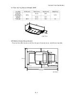
4. Specification
4.1 Base Print Engine Specification
4.1.1 Printing System
Electro-photographic system (roller charging, single component magnetic toner development).
4.1.2 Exposure System
Semiconductor laser beam scanning system.
4.1.3 Transfer System
Roller transfer system.
4.1.4 Fixing System
Thermal fusing system by a heated roller.
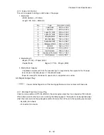
4.1.5 Resolution
600 dpi or 1200 dpi (Dual laser beam, 600 dpi/1200 dpi switch-able at full engine speed).
4.1.6 Warm-up Time
The Print Engine shall reach a READY state within 17 sec maximum after the application of power as a
nominal voltage (120V/220V).
: measured at 22
o
C.
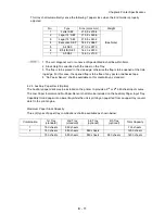
4.1.7 First Print Output Time (FPOT)
The First Print Output Time (FPOT) shall be defined as the time from when the printer receives a START
signal in the READY state, until a single page is printed and delivered into the output tray, under the
scanning condition (Fuser Ready).
The following data are theoretical values without misfeed margin (0.2 sec.).
:
1. SEF: Short Edge Feed
2. Duplex: 1 sht.Batch Mode
3. FPOT from sleep mode
Configuration
Paper
Size
Mode
Tray 1
(t sec)
Tray 2
(t sec)
Tray 3
(t sec)
Tray 4
(t sec)
Tray 2
Exit
550
500
Letter
SEF
Simplex
7.9
7.9
7.9
8.2
Duplex
11.1
11.1
11.1
11.3
A4 SEF
Simplex
7.9
7.9
7.9
8.2
Duplex
11.2
11.2
11.2
11.4
Configuration
Paper
Size
Mode
Tray 1
(t sec)
Tray 2
(t sec)
Tray 3
(t sec)
Tray 4
(t sec)
Tray 2
Exit
550
500
Letter
SEF
Simplex
24.9
24.9
24.9
25.2
Duplex
28.1
28.1
28.1
28.3
A4 SEF
Simplex
24.9
24.9
24.9
25.2
Duplex
28.2
28.2
28.2
28.4
Содержание 9045N
Страница 1: ...Laser Printer TallyGenicom 9045N Service Manual J20006AA ...
Страница 16: ...xv Blank Page ...
Страница 20: ...Chapter 1 Troubleshooting Chapter 1 Troubleshooting CONTENTS Blank Page ...
Страница 88: ...1 68 Chapter 1 Troubleshooting Blank Page ...
Страница 160: ...1 140 Chapter 1 Troubleshooting Blank Page ...
Страница 162: ...1 142 Chapter 1 Troubleshooting Blank Page ...
Страница 164: ...Chapter 2 Printer Diagnostics Chapter 2 Diagnostics CONTENTS 11 Print Summary 2 16 ...
Страница 194: ...1 10 Chapter 3 Removal and Replacement Procedures RRPs RRP2 150 PAPER CASSETTE ...
Страница 213: ...1 29 Chapter 3 Removal and Replacement Procedures RRPs RRP3 550 PAPER CASSETTE ...
Страница 240: ...1 56 Chapter 3 Removal and Replacement Procedures RRPs RRP4 150 paper Feeder ...
Страница 257: ...1 73 Chapter 3 Removal and Replacement Procedures RRPs RRP5 550 Paper Feeder ...
Страница 277: ...1 93 Chapter 3 Removal and Replacement Procedures RRPs RRP6 Xerographics ...
Страница 302: ...1 118 Chapter 3 Removal and Replacement Procedures RRPs RRP7 500 Paper Exit ...
Страница 322: ...1 138 Chapter 3 Removal and Replacement Procedures RRPs RRP8 Frame Drive ...
Страница 331: ...1 147 Chapter 3 Removal and Replacement Procedures RRPs RRP9 Electrical ...
Страница 394: ...1 210 Chapter 3 Removal and Replacement Procedures RRPs ...
Страница 403: ...1 219 Chapter 3 Removal and Replacement Procedures RRPs 4 Install the 550 FEEDER OPTION PL 12 2 RRP12 1 ...
Страница 454: ...1 270 Chapter 3 Removal and Replacement Procedures RRPs Blank Page ...
Страница 456: ...Chapter 4 Plug Jack P J Connector Locations Chapter 4 Plug Jack P J Connector Locations CONTENTS Blank Page ...
Страница 459: ...4 3 Chapter 4 Plug Jack P J Connector Locations Blank Page ...
Страница 465: ...4 9 Chapter 4 Plug Jack P J Connector Locations 3 2 OCT Option P J Diagram ...
Страница 468: ...4 12 Chapter 4 Plug Jack P J Connector Locations Blank Page ...
Страница 470: ...Chapter 5 Parts Lists Chapter 5 Parts Lists CONTENTS Blank Page ...
Страница 472: ...5 2 Chapter 5 Parts List PL 1 1 COVER ILLUSTRATION 2 Ref PL10 1 1 7 8 9 9 13 14 15 3 4 6 5 J25014AA 10 16 J244 ...
Страница 479: ...5 9 Chapter 5 Parts List Blank Page ...
Страница 483: ...5 13 Chapter 5 Parts List Blank Page ...
Страница 490: ...5 20 Chapter 5 Parts List PL 7 2 500 PAPER EXIT 2 2 OPTION FACE UP TRAY ILLUSTRA TION ...
Страница 496: ...5 26 Chapter 5 Parts List OPTIONS PL 10 1 OPTION DUPLEX ILLUSTRATION ...
Страница 501: ...5 31 Chapter 5 Parts List Blank Page ...
Страница 529: ...6 19 Chapter 6 Principles of Operation J26119AA EP CARTRIDGE BTR ASSY ...
Страница 531: ...6 21 Chapter 6 Principles of Operation LD Assembly JG6121AA SOS PWB Scanner Assembly ...
Страница 535: ...6 25 Chapter 6 Principles of Operation ...
Страница 547: ...6 37 Chapter 6 Principles of Operation J26615AA PWBA DUPLEX SWITCH DUPLEX SENSOR DUP MOTOR DUPLEX ROLL DUP FAN DUPLEX ...
Страница 558: ...6 48 Chapter 6 Principles of Operation Blank Page ...
Страница 560: ...Chapter 7 Wiring Diagrams and Signal Information Chapter 7 Wiring Diagrams and Signal Information CONTENTS Blank Page ...
Страница 584: ...7 24 Chapter 7 Wiring Diagrams and Signal Information Blank Page ...
Страница 608: ...Chapter 9 ESS Options Chapter 9 Controller ESS Options Contents Blank Page ...
Страница 616: ...9 8 Chapter 9 ESS Options Blank Page ...


