


4 – 1
Chapter 4 Plug/Jack(P/J) Connector Locations
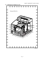
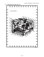
Chapter 4 Print Engine Plug/Jack Connector Locations
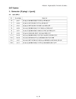
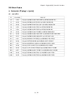
1. Connector [P (plug) / J (jack)]
1.1 List of P/J
P/J Coordinates
Remarks
1
G-104
Connects OPERATION PANEL and HARNESS ASSY PANEL
10
B-111
Connects HARNESS ASSY LVPS and HVPS/MCU
11
D-111
Connects HARNESS ASSY LVPS and HVPS/MCU
13
E-111
Connects HARNESS ASSY ROS and HVPS/MCU
14
E-112
Connects HARNESS ASSY ROS and HVPS/MCU
15
F-112
Connects HARNESS ASSY ANT and HVPS/MCU
16
G-111
Connects HARNESS ASSY ROS and HVPS/MCU
17
G-111
Connects HARNESS ASSY ROS and HVPS/MCU
18
F-112
Connects HARNESS ASSY LVPS and HVPS/MCU
20
H-111
Connects HARNESS ASSY FDR1 and HVPS/MCU
22
I-110
Connects HARNESS ASSY TONER1 and HVPS/MCU
24
J-110
Connects HARNESS ASSY CHUTE and HVPS/MCU
26
I-110
Connects HARNESS ASSY LOW PAPER SNR and HVPS/MCU
27
D-111
Connects HARNESS ASSY LVPS and HVPS/MCU
28
K-110
Connects FFC ASSY ESS and HVPS/MCU
29
K-108
Connects HARNESS ASSY EXIT SNR1 and HVPS/MCU
30
K-107
Connects HARNESS ASSY OCT1 and HVPS/MCU
31
C-111
Connects GUIDE ASSY CRU and HVPS/MCU
40
X-121
Connects HARNESS ASSY LVPS and LVPS
41
X-122
Connects HARNESS ASSY LVPS and LVPS
42
W-122
Connects HARNESS ASSY LVPS and LVPS
43
X-122
Connects MAIN MOTOR and LVPS
44
X-123
Connects INTERLOCK SW REAR and LVPS
45
X-123
Connects INTERLOCK SW 24V and LVPS
46
X-120
Connects HARNESS ASSY FUSER and LVPS
47
U-126
Connects HARNESS ASSY FUSER and LVPS
48
U-125
Connects HARNESS ASSY 100V and LVPS
101
V-120
Connects LVPS and PWBA EXIT MOTOR
102
U-120
Connects HARNESS ASSY LVPS and PWBA EXIT MOTOR
103
S-119
Connects MOTOR ASSY EXIT and PWBA EXIT MOTOR
131
B-111
Connects ROS ASSY and HARNESS ASSY ROS
Содержание 9045N
Страница 1: ...Laser Printer TallyGenicom 9045N Service Manual J20006AA ...
Страница 16: ...xv Blank Page ...
Страница 20: ...Chapter 1 Troubleshooting Chapter 1 Troubleshooting CONTENTS Blank Page ...
Страница 88: ...1 68 Chapter 1 Troubleshooting Blank Page ...
Страница 160: ...1 140 Chapter 1 Troubleshooting Blank Page ...
Страница 162: ...1 142 Chapter 1 Troubleshooting Blank Page ...
Страница 164: ...Chapter 2 Printer Diagnostics Chapter 2 Diagnostics CONTENTS 11 Print Summary 2 16 ...
Страница 194: ...1 10 Chapter 3 Removal and Replacement Procedures RRPs RRP2 150 PAPER CASSETTE ...
Страница 213: ...1 29 Chapter 3 Removal and Replacement Procedures RRPs RRP3 550 PAPER CASSETTE ...
Страница 240: ...1 56 Chapter 3 Removal and Replacement Procedures RRPs RRP4 150 paper Feeder ...
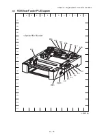
Страница 257: ...1 73 Chapter 3 Removal and Replacement Procedures RRPs RRP5 550 Paper Feeder ...
Страница 277: ...1 93 Chapter 3 Removal and Replacement Procedures RRPs RRP6 Xerographics ...
Страница 302: ...1 118 Chapter 3 Removal and Replacement Procedures RRPs RRP7 500 Paper Exit ...
Страница 322: ...1 138 Chapter 3 Removal and Replacement Procedures RRPs RRP8 Frame Drive ...
Страница 331: ...1 147 Chapter 3 Removal and Replacement Procedures RRPs RRP9 Electrical ...
Страница 394: ...1 210 Chapter 3 Removal and Replacement Procedures RRPs ...
Страница 403: ...1 219 Chapter 3 Removal and Replacement Procedures RRPs 4 Install the 550 FEEDER OPTION PL 12 2 RRP12 1 ...
Страница 454: ...1 270 Chapter 3 Removal and Replacement Procedures RRPs Blank Page ...
Страница 456: ...Chapter 4 Plug Jack P J Connector Locations Chapter 4 Plug Jack P J Connector Locations CONTENTS Blank Page ...
Страница 459: ...4 3 Chapter 4 Plug Jack P J Connector Locations Blank Page ...
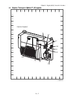
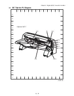
Страница 465: ...4 9 Chapter 4 Plug Jack P J Connector Locations 3 2 OCT Option P J Diagram ...
Страница 468: ...4 12 Chapter 4 Plug Jack P J Connector Locations Blank Page ...
Страница 470: ...Chapter 5 Parts Lists Chapter 5 Parts Lists CONTENTS Blank Page ...
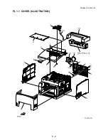
Страница 472: ...5 2 Chapter 5 Parts List PL 1 1 COVER ILLUSTRATION 2 Ref PL10 1 1 7 8 9 9 13 14 15 3 4 6 5 J25014AA 10 16 J244 ...
Страница 479: ...5 9 Chapter 5 Parts List Blank Page ...
Страница 483: ...5 13 Chapter 5 Parts List Blank Page ...
Страница 490: ...5 20 Chapter 5 Parts List PL 7 2 500 PAPER EXIT 2 2 OPTION FACE UP TRAY ILLUSTRA TION ...
Страница 496: ...5 26 Chapter 5 Parts List OPTIONS PL 10 1 OPTION DUPLEX ILLUSTRATION ...
Страница 501: ...5 31 Chapter 5 Parts List Blank Page ...
Страница 529: ...6 19 Chapter 6 Principles of Operation J26119AA EP CARTRIDGE BTR ASSY ...
Страница 531: ...6 21 Chapter 6 Principles of Operation LD Assembly JG6121AA SOS PWB Scanner Assembly ...
Страница 535: ...6 25 Chapter 6 Principles of Operation ...
Страница 547: ...6 37 Chapter 6 Principles of Operation J26615AA PWBA DUPLEX SWITCH DUPLEX SENSOR DUP MOTOR DUPLEX ROLL DUP FAN DUPLEX ...
Страница 558: ...6 48 Chapter 6 Principles of Operation Blank Page ...
Страница 560: ...Chapter 7 Wiring Diagrams and Signal Information Chapter 7 Wiring Diagrams and Signal Information CONTENTS Blank Page ...
Страница 584: ...7 24 Chapter 7 Wiring Diagrams and Signal Information Blank Page ...
Страница 608: ...Chapter 9 ESS Options Chapter 9 Controller ESS Options Contents Blank Page ...
Страница 616: ...9 8 Chapter 9 ESS Options Blank Page ...


