background image


Controlling with External Analog & Contact Signals 


153 

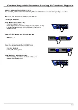
LEVEL1_ALM, 

This handles the operation mode’s status signal as a LEVEL1_ALM (alarm status). 
It can also be used for surveillance as an alarm when switching from constant voltage to constant current. 


Status Signals that can be set in LEVEL1_ALM 

CV_STS (Constant Voltage Operation) 
CC_STS (Constant Current Operation) 


Setting Procedures 


Press the Function "FUNC." key. 

The FUNC. lamp will light. 
The Setting Item Number will be displayed in the Number Display 
(voltage) and the parameter will be displayed in the Number 
Display (current). 


Select the Item number with the VOLTAGE dial. 


Item 74 : CV_STS 
Item 75 : CC_STS 


Select the parameter with the CURRENT dial. 

 
0=Not included in LEVEL1_ALM [Default] 
1=Included in LEVEL1_ALM 


Press the FUNC. key again to finish. 

Confirms settings and returns the Number Display to 
measurement display mode. 


Содержание HX-S-G4 Series

Страница 1: ...ss co jp Constant Voltage Constant Current DC Power Supply HX S G4 series Instruction Manual HX S 030 200G4 HX S 030 400G4 HX S 060 100G4 HX S 060 200G4 HX S 0500 12G4 HX S 0500 24G4 HX S 01000 6G4 HX...

Страница 2: ...iew 59 Display during sequential operation 66 e g 1 Setting of sequential operation 67 e g 2 Setting of sequential operation 68 Using Via Digital Data Communication 69 Summary 69 Multiple Connections...

Страница 3: ...ternal Resistance C 172 Offset Full Scale Calibration of Output Current with External Analog Input 174 Output Current Control with External Voltage Isolated External Voltage 174 Output Current Control...

Страница 4: ...ymbol and improper use or handling of the product may result in injury or property damage Items that must be observed are classified into the following marks This mark indicates items that are Prohibi...

Страница 5: ...to carry the this equipment Turn off the input power switch POWER and remove all cables from the main body beforehand Hold the bottom surface during carrying Do not hold the handles on both sides The...

Страница 6: ...control also grants settings with superior accurate reproduction 125 100 75 50 12 6 0 18 24 30 0 50 100 150 200 250 300 350 400 Output Voltage V Output Current A HX030 200 HX030 400 30V Output Type 2...

Страница 7: ...nting current overshoot when output is ON Sequential ON OFF Sets the order outputs are toggled ON OFF through a multi connection cable Protection Functions Guards valuable loads and power supplies wit...

Страница 8: ...tting status with keys A B and C Also depending on the Function item setting this can be used to select One Action or Two Action loading method LOCK LOCK Key Locks panel from use Lights when Lock has...

Страница 9: ...as been transferred to an external computer etc being accessed via serial interface Number Display Voltage Displays the output voltage and the output power When setting functions with the Function key...

Страница 10: ...r for parallel operations TERMINATION Termination Resistor ON OFF Switch When controlling one unit of this product via serial port please set the termination toggle switch to ON When using 2 or more p...

Страница 11: ...6 HX01000 12 DC OUTPUT terminal Always use crimp terminals please firmly tighten the screws Please Once connected sure to attach the output terminal cover REMOTE SENSE terminal Remote sensing terminal...

Страница 12: ...the DC OUTPUT terminal on the rear panel at the time of shipment 10 Output Terminal Cover for 30 200 and 60V type 1 set Two same shape Output Terminal Covers A support for mounting cover Two M3 x 6mm...

Страница 13: ...see below for proper placement How to place Mandatory Use only in areas with a room temperature of 0 50 humidity of 20 90 RH and which is absent of any corrosive gases Prohibited This power supply us...

Страница 14: ...not available Please use three phase four wire system Set circuit breaker between feeding device and this equipment Connect the circuit breaker to the feeding device and the equipment The input power...

Страница 15: ...2 AWG12 more HX030 400 HX060 200 HX0500 24 HX01000 12 8mm2 AWG8 more Insert the wire into the connector Secure the cable to tighten at screw tightening torque 0 5 0 6Nm Connect the cable for the groun...

Страница 16: ...Secure it by tightening the top and bottom two places screws so that it is not missing is inserted connector Photo is Fixed under the screws Secure it by tightening the top and bottom two places scre...

Страница 17: ...one at the load end Wiring material Do wiring material twisting Route as close as much as possible M12 Bolt M12 Crimping terminal Protective tube Insulation lock Output terminal cover 500V 1000V Type...

Страница 18: ...or load currents For selecting wires refer to Appendix 4 Load Current vs Recommended Cross Section Area page214 Mandatory Attach crimp style terminals to wires and securely fasten If insecurely fasten...

Страница 19: ...identical in shape Insert the supporter for attaching into the center part of the inside of the output terminal cover and fix it in place by screwing an M3x6mm from outside 2 Connect the cable to the...

Страница 20: ...attaching cover has been attached on the left side grooves of the output terminal 5 Fix the other output terminal cover on the right side grooves of the output terminal 6 Fasten the output terminal c...

Страница 21: ...er by joining the wire bands together using four M3 x 6mm screws 2 The upper and lower output terminal cover can be checked from the front of the cover Please refer to the following 3 Snap the termina...

Страница 22: ...Preparation and Connection 22 4 To finish the installation use the 2 M3 x 6mm screws to fix the top and bottom terminal covers together M3x6mm Screw...

Страница 23: ...ert the supporter for attaching into the center part of the inside of the output terminal cover and fix it in place by screwing an M3x6mm from outside 2 Fix the output terminal cover to which the supp...

Страница 24: ...Preparation and Connection 24 4 Fasten the output terminal covers with an M3X6mm screw 5 Attaching the output terminal cover is completed...

Страница 25: ...isplay voltage and the current total output capacity will appear blinking on the Number Display current After confirming the total output capacity if you hold down the FUNC key for more than 2 seconds...

Страница 26: ...rrent Set Value 12 60A 25 20A 6 300A 12 60A Over Voltage Protection OVP Set Value 550 0V 550 0V 1100V 1100V Over Current Protection OCP 13 20A 26 40A 6 600A 13 20A Settings Values in Memory A B C Same...

Страница 27: ...ower the set value If the parameter for FUNCTION item 50 is set to 0 press the PRESET key again The output voltage will be updated once the PRESET mode has been exited If the parameter for FUNCTION it...

Страница 28: ...settings and returns to the measurement display mode Press the OUTPUT key Outputs with the set settings The OUTPUT and CV lamps will light While the PRESET lamp is lit all other keys not mentioned in...

Страница 29: ...ht to raise or left to lower the set value If the parameter for FUNCTION item 50 is set to 0 press the PRESET key again The output current will be updated once the PRESET mode has been exited If the p...

Страница 30: ...settings and returns to the measurement display Press the OUTPUT key Outputs with the set settings The OUTPUT and the CC lamp will light While the PRESET lamp is lit all other keys not mentioned in t...

Страница 31: ...ER While using remote sensing do not switch output lines using switches etc Doing so may lead to damaging the power supply Because the output terminal s voltage is detected by the OVP circuit please s...

Страница 32: ...g Procedures Press The Function FUNC key The FUNC lamp will light The Setting Item Number will be displayed in the Number Display voltage and the parameter will be displayed in the Number Display curr...

Страница 33: ...Output Current x 2 s This function can be set for full featured type model name with F only 5 CC Slew Rate Falling 6 Serial I F2 0 Serial Data Communication Control Remote Mode 0 Serial Data Communic...

Страница 34: ...tage Monitor Output Full Scale Not displayed 34 Current Monitor Output Offset Not displayed 35 Current Monitor Output Full Scale Not displayed 36 Not displayed 37 Voltage offset when series slave Not...

Страница 35: ...Panel 0 Front Panel Function of 2 to 4 It is impossible to use HX S 01000 G4 1 External Voltage 0 10V 2 External Resistance 0 10k A 3 External Resistance 0 10k B 4 External Resistance 0 10k C 71 CC Co...

Страница 36: ...6 Over Heating Protection OHP B05 Over Voltage Protection OVP B04 Over Current Protection OCP 1st digit B03 B02 B01 Status of Constant Current CC B00 Status of Constant Voltage CV 81 Status Display 2...

Страница 37: ...STEP 2 SWEEP 118 Sequential Operation Step 2 Control Time Minute 0 9999 minutes 0 minute 119 Sequential Operation Step 2 Control Time 0 1 sec 0 59 9 sec 0 second 120 Sequential Operation Step 3 Pre s...

Страница 38: ...Time 0 1 sec 0 59 9 sec 0 second 145 Sequential Operation Step 8 Pre set CV value 0V Max of each model 0 00V 146 Sequential Operation Step 8 Pre set CC value 0A Max of each model 0 0A 147 Sequential O...

Страница 39: ...played in the bottom Number Display Select Item number 51 with the VOLTAGE dial Set Parameter to 0 1 or 2 with the CURRENT dial Parameter 0 Output is OFF COLD START after power is turned on Pressing t...

Страница 40: ...e complete please follow the procedures below to test verify operation Disconnect the load from the power supply Turn the POWER switch ON with the Output ON OFF Toggle mode FUNC 51 set to 0 Set the Ou...

Страница 41: ...start output When the OVP is triggered the Falling slew rate setting by the slew rate function becomes invalid and the voltage is decreased most rapidly under the condition of that time point MEMO Du...

Страница 42: ...wires that can flow rated current Turn the POWER switch ON with the Output ON OFF Toggle mode FUNC 51 set to 0 Set the Output Current settings lower than OCP level Turn OUTPUT to ON Gradually increas...

Страница 43: ...put When the OCP is triggered the Falling slew rate setting based on the slew rate function is set invalid and the output current is decreased most rapidly under the condition of that time point MEMO...

Страница 44: ...in the bottom Number Display Select Item number 9 with the VOLTAGE dial Set Parameter to 0 1 or 2 with the CURRENT dial Parameter 0 Default value When any alarm occurs switching is stopped forced outp...

Страница 45: ...se check the wiring connection to the input connector Device Detection Error E009 Cannot detect number of parallel devices Restart power supply No of Parallel Connected Devices Over E010 More than 11...

Страница 46: ...ill return to measurement display mode Loading from Memory Single Action Loading Set the parameter for FUNCTION settings item 54 to 0 See page 35 Function Settings on how Press the memory key you wish...

Страница 47: ...n the memory key to be loaded for more than 1 second The light will blink faster until finished Once loading is complete the display will return to measurement display mode Panel Memory Savable Settin...

Страница 48: ...sing as a normal constant voltage power supply for testing equipment and devices 2 Constant Current CC Priority Mode High Medium Low speed Perfect when wishing to control the current of the load such...

Страница 49: ...rallel devices Rated Output Current Io Range Resolution Io 50A 0 01 to Twice the constant output current A s 0 01A 50A Io 500A 0 1 to Twice the constant output current A s 0 1A 500A Io 4000A 1 to Twic...

Страница 50: ...Set Value 5 Falling Current Slew Rate Assign the set value using the CURRENT dial Range Ex 0 1A s to 400 0A s Resolution 0 1A s If using in parallel operation Constant Current CC Slew Rate in page 49...

Страница 51: ...or multiple HX S G4 Series power supplies simultaneously or using time delays Optional cables T485 M are required for connection Sold separately Sequential ON OFF Connection ON OFF TERMINATION ON ON O...

Страница 52: ...n the Number Display voltage and the parameter will be displayed in the Number Display current Select Item Number 6 with the VOLTAGE dial then set the parameter to 1 with the CURRENT dial Set the Dela...

Страница 53: ...e Master and Slave settings with the CURRENT dial Set the Master to the address 1 Set the Slave to a setting other than the address 1 If there are more than one slaves set the addresses avoiding addre...

Страница 54: ...lected under the FUNCTION Settings Item Number 53 parameters from the following 3 types below Parameter 0 Only the LOCK key can be used Parameter 1 Only the OUTPUT key and LOCK key can be used Paramet...

Страница 55: ...FUNC lamp will light The Setting Item Number will be displayed in the Number Display voltage and the parameter will be displayed in the Number Display current Select Item number 72 with the VOLTAGE d...

Страница 56: ...ximately every 200ms This method is known as the Moving Average Method Setting Procedures Press The Function FUNC key The FUNC lamp will light The Setting Item Number will be displayed in the Number D...

Страница 57: ...ng Item Number will be displayed in the Number Display voltage and the parameter will be displayed in the Number Display current Select Item number 12 with the VOLTAGE dial and Select the operation mo...

Страница 58: ...eter will be displayed in the Number Display current Setting Beep Sound for Pressing Buttons Set the parameter to 90 with the VOLTAGE dial and perform setting with the CURRENT dial 1 With beep sound D...

Страница 59: ...ved by the sequential operation function Control output by setting preset CV CC value control contents STEP or SWEEP and control time 0 1 sec 9999 min 59 9 sec to each steps from step 1 to step 10 ref...

Страница 60: ...s some time to start OUTPUT in actual at OUTPUT ON state due to characteristic of internal circuit Please take note the control time after OUTPUT ON will be not as set Reference time to output the des...

Страница 61: ...orm will be the following image when the programing time e g Model 500V type and CV low speed 500ms is longer than control time e g 0 1s Please take note that the waveform dose not rise vertically reg...

Страница 62: ...1s STEP control Step 2 STEP control Step 3 STEP control Preset CV value 0V Preset CC value 0A Please set the value as shown on the left to set less than 1 sec such as 0V and 0A Voltage Current Elapsed...

Страница 63: ...e power supply for constant voltage CV setting Please refer to page 29 Use as constant current power supply for constant current CC setting Set value for Over Voltage Protection OVP and Over Current P...

Страница 64: ...to the sequential operation for STEP 1 Keep the function key FUNC pressed and select 110 for parameter with VOLTAGE dial and set the desired Preset CV value with CURRENT dial Keep the function key FUN...

Страница 65: ...interval during sequential operation Set Preset CV value Preset CC value Control contents and Control time to the sequential operation after STEP 2 Please refer to page37 FUNCTION setting for sequent...

Страница 66: ...t Measurement Value Voltage Measurement Value Current Measurement Value Repetition Sequential Operation Voltage Measurement Value Current Measurement Value Voltage Measurement Value Current Measuremen...

Страница 67: ...al operation mode 2 Enable Continue 116 Sequential operation No 2 Preset CC value 10 0 A 101 Number of repetition of sequential operation 3 117 Sequential operation No 2 Control contents 2 SWEEP 102 O...

Страница 68: ...Sequential operation No 3 Preset CC value 10 0 A 110 Sequential operation No 1 Preset CV value 5 V 122 Sequential operation No 3 Control contents 2 SWEEP 111 Sequential operation No 1 Preset CC value...

Страница 69: ...HX S G Series Commands External Control Connector SERIAL I F 1 Connector Types RS 232C 3 5 7 9 Pin No 1 TX GND RTS NC Name NC OUT OUT IN OUT 4 6 8 Pin No 2 DTR DSR CTS Name RX OUT IN IN OUT IN Extern...

Страница 70: ...ower supplies on multiple channels via computer When connecting multiple HX S G4 Series power supplies only one communication terminal computer etc can be connected Be sure to set the device address t...

Страница 71: ...cannot be established if settings differ Set the bitrate and parity under FUNCTION Setting Item 61 Bitrate and Item 62 Parity Setting changes will take effect from next startup Command Send Interval W...

Страница 72: ...eived control via communication commands from that point will be released Again when controlling via communication commands command controls will take effect once the device address has been set with...

Страница 73: ...f RS 485 control set to other than 1 PC Set voltage to 5 5V for HX S G4 power supply with device address set to 1 RS 232C RS 485 Connection Configuration Device Address 1 Device Address 2 Note If RS 4...

Страница 74: ...l commands and responses are ASCII character strings One character space is required between command words and parameters Ex ADDRess 1 Within text command word stands for command characters such as AD...

Страница 75: ...l command Inputting SCPI Commands SCPI commands use the following hierarchical structure Ex ALM Root Command CLEar Command CONTain Pass Command CC NRf Command Parameters NRf is a numeric parameter Omi...

Страница 76: ...end of the program message CR LF CR LF CR Carriage Return 0x0d LF Line Feed 0x0A Executing Commands Commands will be executed in the order in which they appear in the program message Invalid commands...

Страница 77: ...T Resets set parameters SET Only IDN Identification Query Function Retrieves device information Name of Manufacturer Name of Model Software Version Format IDN Type QUERY command only Response Name of...

Страница 78: ...tion Assigns the device address for HX S G4 power supplies Format ADDRess NRf Type SET command only Range 0 50 Address 0 is a global address Assign addresses to all multi connected HX S G4 Series DC p...

Страница 79: ...t ALM CLEar Type SET command only No parameters Ex ALM CLE ALM CONTain CC Sets whether to contain CC_STS in LEVEL1_ALM Function Sets whether to contain CC_STS status in LEVEL1_ALM output condition Sam...

Страница 80: ...ame as FUNCTION Settings Item 74 Format ALM CONTain CV NRf Type SET command QUERY command Parameters 0 Does not include in LEVEL1_ALM 1 Includes in LEVEL1_ALM Response 0 1 Restrictions Alarm response...

Страница 81: ...onse Same as parameters Restrictions Alarm response is returned for normal SET commands in the following conditions Cases other than full featured type model name with F While operating as a series op...

Страница 82: ...as a parallel operation slave unit While operating as a series operation slave unit Ex OUTP EXT MODE 1 OUTP EXT MODE 1 OUTPut HOT Sets Output status while POWER is ON Function Sets Output status while...

Страница 83: ...is returned for normal SET commands in the following conditions Cases other than full featured type model name with F While operating as a series operation slave unit While operating as a parallel ope...

Страница 84: ...es QUERY Only POWer DC Retrieves power measurement values QUERY Only MEASure CORRection MODE Sets operation mode for the Linearity Compensation Function Function Sets the operation mode for the Linear...

Страница 85: ...Ex MEAS MVAV 0 MEAS MVAV 0 MEASure SCALar CURRent DC Retrieves Current Measurement Values Function Retrieves current measurement values Format MEASure SCALar CURRent DC Type QUERY command only Respons...

Страница 86: ...ieves electric power measurement values Format MEASure SCALar POWer DC Type QUERY command only Response Returns same resolution data as the power meter Restrictions Alarm response is returned for norm...

Страница 87: ...LEVel Sets OCP Current Both SLEW RISing Sets CC Slew Rate Rising Both FALLing Sets CC Slew Rate Falling Both MEMory RECall Loads from Panel Memory SET Only MODE Sets Loading Order for Panel Memory Bot...

Страница 88: ...6kW 0 to 1260 0 0 to 630 0 0 00 to 75 60 0 00 to 37 80 42kW 0 to 1470 0 0 to 735 0 0 00 to 88 20 0 00 to 44 10 48kW 0 to 1680 0 0 to 840 0 0 0 to 100 8 0 0 to 50 40 54kW 0 to 1890 0 0 to 945 0 0 0 to...

Страница 89: ...0 42kW 14 0 to 1540 7 0 to 770 0 0 84 to 92 40 0 42 to 46 20 48kW 16 0 to 1760 8 0 to 880 0 1 0 to 105 6 0 48 to 52 80 54kW 18 0 to 1980 9 0 to 990 0 1 1 to 118 8 0 54 to 59 40 60kW 20 0 to 2200 10 0...

Страница 90: ...42kW 0 to 2800 0 to 1400 0 1 to 168 0 0 42 to 46 20 48kW 0 to 3200 0 to 1600 0 1 to 192 0 0 48 to 52 80 54kW 0 to 3600 0 to 1800 0 1 to 216 0 0 54 to 59 40 60kW 0 to 4000 0 to 2000 0 1 to 240 0 0 60 t...

Страница 91: ...featured type model name with F While operating as a series operation slave unit While operating as a parallel operation slave unit Ex CURR SLEW FALL 400 0 CURR SLEW FALL 200 0 SOURce MEMory RECall L...

Страница 92: ...conditions While operating as a series operation slave unit While operating as a parallel operation slave unit Ex MEM REC MODE 1 MEM REC MODE 1 SOURce MEMory STORe Saves to Panel Memory Function Saves...

Страница 93: ...0 0 2 0 to 100 1 0 to 6 94 0 05 0 to 27 8 0 2 42kW 0 to 21 4 0 2 0 to 86 1 0 to 5 95 0 05 0 to 23 8 0 2 48kW 0 to 18 8 0 2 0 to 75 0 0 5 0 to 5 21 0 05 0 to 20 8 0 2 54kW 0 to 16 7 0 2 0 to 66 7 0 5...

Страница 94: ...in the following conditions While operating as a series operation slave unit While operating as a parallel operation slave unit Ex VOLT 30 VOLT 30 00 SOURce VOLTage PROTection LEVel Sets OVP voltage...

Страница 95: ...LTage SLEW FALLing Sets CV Slew Rate Falling Function Sets the CV slew rate for falling Same as FUNCTION Settings Item 3 Format SOURce VOLTage SLEW FALLing NRf Type SET command QUERY command Parameter...

Страница 96: ...Status 1 Above OCP level Below OCP level 13 Not Used Always 0 12 EXT_ON Toggling Output ON OFF at External Contacts Input Status ON OFF 11 ALM_BUS_STS SYS_ALM System error Error Normal 10 DD_ON_BUS_ST...

Страница 97: ...SET command QUERY command Parameter LEVEL1_ALM OUTPUT ON OFF_STS Response Same as parameters Restrictions Alarm response is normally returned to set command under the following state Alarm is occurrin...

Страница 98: ...analog control signals Both VOLTage MODE Sets mode for Voltage Settings Control Method Both ISOLate Isolated of external analog control signals Both ERRor NEXT Reads Error Message QUERY Only KEYLock M...

Страница 99: ...e unit While operating as a parallel operation slave unit Ex SYST COMM SER BAUD 3 SYST COMM SER BAUD 38400 SYSTem COMMunicate SERial RECeive PACE Sets Acknowledge Response Function sets the Acknowledg...

Страница 100: ...its to the Query Response Format SYSTem COMMunicate SERial UNIT NRf Type SET command QUERY command Parameters 0 Do not add units Default Settings 1 Add on units Response Same as parameters Explanation...

Страница 101: ...e operating as a series operation slave unit While operating as a parallel operation slave unit Ex SYST CONT CURR MODE 1 SYST CONT CURR MODE 1 SYSTem CONTrol CURRent ISOLate Sets Isolation for externa...

Страница 102: ...e operating as a series operation slave unit While operating as a parallel operation slave unit Ex SYST CONT VOLT MODE 1 SYST CONT VOLT MODE 1 SYSTem CONTrol VOLTage ISOLate Sets isolation for externa...

Страница 103: ...ror 104 Data type error Data type error Character received instead of numeral in parameter etc 108 Parameter not allowed Too many parameters 109 Missing parameter Too few parameters 120 Numeric data e...

Страница 104: ...owing conditions While operating as a series operation slave unit While operating as a parallel operation slave unit Ex SYST KEYL MODE 1 SYST KEYL MODE 1 SYSTem MONitor MODE Sets Voltmeter Ammeter Dis...

Страница 105: ...al SET commands in the following conditions While operating as a series operation slave unit While operating as a parallel operation slave unit Ex SYST PRES MODE 0 SYST PRES MODE 0 SYSTem SERies Sets...

Страница 106: ...or serious failure or when OVP OCP triggered Restrictions Alarm response is returned for normal SET commands in the following conditions While operating as a parallel operation slave unit Ex SYST TRIP...

Страница 107: ...uery about System Capacity kW Function Retrieves the system capacity kW Format SYSTem POWer Type QUERY command only No parameters Response System capacity kW Restrictions None Ex SYST POW 6 SYSTem STO...

Страница 108: ...for sequential operation Function Set operation mode of DC power supply operation and sequential operation Same as FUNCTION Setting Item 100 Format SEQuence MODE NR1 Type SET command QUERY command Pa...

Страница 109: ...ET command QUERY command Parameter 0 9999 Note 0 Operation will be looped unless any termination request Response Same as parameters Restrictions Alarm response is returned for normal SET commands in...

Страница 110: ...ue note Setting range is depended on the DC power supply Control Time min 0 9999 Control Time sec 0 0 59 9 Control contents 0 OUT OFF 1 STEP 2 SWEEP QUERY command Sequential operation line 1 10 Respon...

Страница 111: ...urring Sequential operation is in progress Power supply is operating as slave machine in serial operation Power supply is operating as slave machine in parallel operation Ex SEQ STOP 0 SEQ STOP 0 SEQu...

Страница 112: ...ge A Assigning Device Address Page 114 AR Executes alarm reset Page 114 CL Resets set parameters Page 114 LC Sets OCP current Page 115 LV Sets OVP voltage Page 115 MC Sets Output Current Page 116 MV S...

Страница 113: ...se is received When undefined command is received When command parameters exceed the range When a character or symbol other than numerals 0 9 and decimal point is sent in parameters When sent with a s...

Страница 114: ...ess 1 Bad Example A1 OT1 A2 OT1 Error due to multiple address assignment commands AR Executes Alarm Reset Function Executes alarm reset Cancels generated Over Voltage Over Current alarm Format AR Set...

Страница 115: ...6 0 to 1760 8 0 to 880 0 1 0 to 105 6 0 48 to 52 80 54kW 18 0 to 1980 9 0 to 990 0 1 1 to 118 8 0 54 to 59 40 60kW 20 0 to 2200 10 0 to 1100 1 1 to 132 0 0 60 to 66 00 66kW 22 0 to 2420 11 0 to 1210 1...

Страница 116: ...42kW 0 to 1470 0 0 to 735 0 0 00 to 88 20 0 00 to 44 10 48kW 0 to 1680 0 0 to 840 0 0 0 to 100 8 0 0 to 50 40 54kW 0 to 1890 0 0 to 945 0 0 0 to 113 4 0 0 to 56 70 60kW 0 to 2100 0 to 1050 0 0 to 126...

Страница 117: ...te input power relay trip When TRIP is detected or severe breakdown 2 Execute input power relay trip When TRIP is detected severe breakdown OVP OCP triggered Values other than 0 1 or 2 result in param...

Страница 118: ...Value For max no of decimal places refer to Output Current Range in page 116 4 Over Voltage Set Value Max no of decimal places is 1 5 Over Current Set Value For max no of decimal places refer to OCP...

Страница 119: ...ecification isolated OP attached A1 TK2 A1 HX S G4FI MV30 00 MC200 0 LV33 00 LC220 0 TK3 Read Back Status Information Function Retrieves the status information from the HX S G4 power supply with the s...

Страница 120: ...Current Data Function Retrieves the measured current data from the HX S G4 power supply with the specified device address Format TK5 Read Back Format A Read Back Value Read Back Value Specified HX S...

Страница 121: ...M Sold Separately 1 Master 2 Slave n Slave Parallel operation is only possible with the same voltage HX S G4 series models Ex Parallel operation of HX S 030 200G4 and HX S 030 400G4 is possible FUNCT...

Страница 122: ...ating normally will display bars as shown on the right CAUTION Error Codes 1 Error Codes Display List for Master Unit Place Items No Display Voltage No Display Current Content WDT E001 Malfunction of...

Страница 123: ...the same Connecting device models that are different in power capacity will result in breakdown Turn all series connected HX S G4 Series input power POWER switch ON Please calibrate the output voltage...

Страница 124: ...l control connector No 9 terminal Connect wires from the Master s isolated control connector No 16 terminal to the Slave s external control connector No 22 terminal The signal lines of and should be s...

Страница 125: ...nt voltage setting value to xV and the constant current setting value to yA and set the output to ON 30V Type 60V Type 500V Type xV 0 01V 0 01V 0 1V yA 1 0A 1 0A 0 1A On how to set see Operating as Co...

Страница 126: ...unit s digital multimeter for output voltage measurement is the same as the display of the Master unit s digital multimeter for output voltage measurement 11 Press the FUNC key of the Slave unit to s...

Страница 127: ...connecting Wire Extract Screwdriver Wire Size 24 16AWG UL Stripped Length 10 0mm 10 0mm 2 5mm 0 4mm How to insert wire into insulation control connector Turn the screw at the upper part of the connec...

Страница 128: ...With Isolation OP 1 Isolation Voltage Monitoring Output No Yes 2 Isolation Common for Voltage Current Monitoring Output No Yes 3 Isolation Current Monitoring Output No Yes 4 Isolation Output Voltage...

Страница 129: ...can be simply removed by pushing down the lock levers on both sides External Control Connector Photocupler or Contact 9 Twisted Pair Wire 22 Open Putput Closed Output Toggling Output ON OFF with Exter...

Страница 130: ...Set this if controlled by the front panel s ON OFF key or by remote control commands Set value 1 Sets Output ON if the external contact is closed and OFF if the external contact is opened Set this if...

Страница 131: ...h with a minimum contact capacity of 5V 2 5mA FUNCTION settings must be changed to Valid for Output ON OFF Control at External Contact Points to be used Factory default settings are set to Invalid Con...

Страница 132: ...Set this if controlled by the front panel s ON OFF key or by remote control command Set value 1 Sets Output ON if the external contact is closed and OFF if the external contact is opened Set this if...

Страница 133: ...ttings are set to Invalid Connecting For the connecting refer to page123 Wire the cables to the isolated control connector accessory terminals No 15 of Slave and the external control connector accesso...

Страница 134: ...Set this if controlled by the front panel s ON OFF key or by remote control command Set value 1 Sets Output ON if the external contact is closed and OFF if the external contact is opened Set this if...

Страница 135: ...es You can choose TRIP operation by short circuit make of contact a and TRIP operation by opening break of contact b MEMO Not suited for power contacts such as main contacts for electromagnetic contac...

Страница 136: ...ntacts 11 24 9 10 a Case of contact a operation selection external control connector No 11 No 24 not connected Closed TRIP b Case of contact a operation selection external control connector No 11 No 2...

Страница 137: ...age 0 2 of Rated Output Voltage when 10k Connection Connect the resistor between No 7 and 20 of the external control connector accessory Setting Procedures Set the parameter to 2 External Resistance T...

Страница 138: ...d the parameter will be displayed in the Number Display current Select Item number 70 with the VOLTAGE dial Select the parameter with the CURRENT dial 0 Front Panel Default 1 External Voltage 0 to 10V...

Страница 139: ...4 and 17 of the external control connector accessory Setting Procedures Set the parameter to 3 External Resistance Type B according to the procedure on page 138 4 17 0 10k Output Voltage Control with...

Страница 140: ...o 4 and 17 of the external control connector accessory Setting Procedures Set the parameter to 4 External Resistance Type C according to the procedure on page 138 4 17 0 10k Output Voltage Control wit...

Страница 141: ...rnal voltage between No 3 and 16 of the external control connector accessory Setting Procedures Set the parameter to 4 External Resistance Type C according to the procedure on page 138 External Voltag...

Страница 142: ...a Output Voltage V 10 Resistance External Voltage Output Maximum The output accuracy for the external voltage is the set voltage 0 2 of Rated Output Voltage Connecting Connect the external voltage bet...

Страница 143: ...rent 1 of Rated Output Current when 10k Connecting Connect the resistor between No 8 and 20 of the external control connector accessory Setting Procedures Set the parameter to 2 External Resistance Ty...

Страница 144: ...he parameter will be displayed in the Number Display current Select Item number 71 with the VOLTAGE dial Select the parameter with the CURRENT dial 0 Front Panel Default 1 External Voltage 0 10V 2 Ext...

Страница 145: ...nal control connector accessory Setting Procedures Set the parameter to 3 External Resistance Type B according to the procedure on page 144 6 19 0 10k External Control Connector Twisted Pair Wire Exte...

Страница 146: ...the external control connector accessory Setting Procedures Set the parameter to 4 External Resistance Type C according to the procedure on page 144 6 19 0 10k External Control Connector Twisted Pair...

Страница 147: ...he external voltage between No 5 and 18 of the external control connector accessory Setting Procedures Set the parameter to 1 External Voltage according to the procedure on page 144 External Control C...

Страница 148: ...derived from the following formula Output Current A 10 Voltage External Voltage Output Max The output accuracy for the external voltage is the set current 1 0 of Rated Output Current Connecting Conne...

Страница 149: ...the output current monitor is 1 0 10mV Connecting Connect the meter or the recorder between No 2 and 15 of the external control connector accessory External Control Connector 1 Twisted Pair Wire 14 V...

Страница 150: ...put Please use an input impedance of a 10k or more for the external meter Isolated Output Voltage Monitor The accuracy for the output voltage monitor is 0 5 10mV Connecting Connect the meter or the re...

Страница 151: ...ccurred OUTPUT ON OFF STS OUT PUT ON OFF has occurred 12 LEVEL2_ALM Alarm has occurred Include Several Alarms 13 CV_STS Running in Constant Voltage Mode 14 CC_STS Running in Constant Current Mode 15 P...

Страница 152: ...ess the Function FUNC key The FUNC lamp will light The Setting Item Number will be displayed in the Number Display voltage and the parameter will be displayed in the Number Display current Select the...

Страница 153: ...S Constant Current Operation Setting Procedures Press the Function FUNC key The FUNC lamp will light The Setting Item Number will be displayed in the Number Display voltage and the parameter will be d...

Страница 154: ...Reverse Current IR Power Supply VO Dummy Resistor R Load When This machine does not have functions to stabilize the output voltage against reverse current from loads If the maximum sink current is ex...

Страница 155: ...rent is in a pulsing state This cannot be determined by this device s ammeter alone because it only displays the average output current value If the constant current circuit power limit circuit is tri...

Страница 156: ...e case of parallel connection If sensing is done with the secondary battery connected and the reverse current blocking diode equipped a potential difference occurs between each output and the sensing...

Страница 157: ...Special Loads 157 This page is blank...

Страница 158: ...roduct number 12 digit number at the rear panel of product and the firmware version For the firmware version refer to page 33 FUNCTION 0 Daily Maintenance and Inspection Please perform periodic inspec...

Страница 159: ...r Remove the front cover and air filter Please remove the front panel by loosing the screws circled red and pulling the panel by nipping the screws Please remove the air filter from the front cover Th...

Страница 160: ...attach the filter to the back side of the front cover note The picture is HX0500 12G4 Insert the positioning parts into the upper hocks on the back side of the front cover Both positioning parts shal...

Страница 161: ...Maintenance 161 This page is blank...

Страница 162: ...OWER switch ON and OUTPUT OFF in advance Power Supply V Digital Multimeter Calibration Circuit 2 Set the constant voltage setting value to xV and the constant current setting value to yA and set the o...

Страница 163: ...mber 21 in the Number Display voltage At that time turn off the Number Display current 10 Adjust so that the output voltage becomes xV with the CURRENT dial 30 200 30 400 60 100 60 200 xV 30 000V 30 0...

Страница 164: ...00V 1 00V 1 00V 1 00V yA 0 1A 0 1A 0 1A 0 1A 500 12 500 24 1000 6 1000 12 xV 1 0V 1 0V 1V 1V yA 0 10A 0 10A 0 010A 0 01A On how to set see Operating as Constant Current Power Supply under Basic Operat...

Страница 165: ...t so that the output current becomes yA with the CURRENT dial 30 200 30 400 60 100 60 200 yA 200 00A 400 00A 100 00A 200 00A DMM display value 50 00mV 40 00mV 25 00mV 50 00mV 500 12 500 24 1000 6 1000...

Страница 166: ...and set the output to ON 30 200 30 400 60 100 60 200 yA 1 0A 1 0A 1 0A 1 0A 500 12 500 24 1000 6 1000 12 yA 0 10A 0 10A 0 010A 0 10A On how to set refer to Output Voltage Control with ExternalVoltage...

Страница 167: ...oltage At that time C or F is displayed in the Number Display current C Coarse adjustment F Fine adjustment 10 Adjust so that the output voltage becomes xV with the CURRENT dial 30 200 30 400 60 100 6...

Страница 168: ...nstant current setting value to yA and set the output to ON 30 200 30 400 60 100 60 200 yA 1 0A 1 0A 1 0A 1 0A 500 12 500 24 1000 6 1000 12 yA 0 10A 0 10A 0 010A 0 10A On how to set refer to Output Vo...

Страница 169: ...ge At that time C or F is displayed in the Number Display current C Coarse adjustment F Fine adjustment 10 Adjust so that the output voltage becomes xV with the CURRENT dial 30 200 30 400 60 100 60 20...

Страница 170: ...nt current setting value to yA and set the output to ON 30 200 30 400 60 100 60 200 yA 1 0A 1 0A 1 0A 1 0A 500 12 500 24 1000 6 1000 12 yA 0 10A 0 10A 0 010A 0 10A On how to set refer to Output Voltag...

Страница 171: ...age At that time C or F is displayed in the Number Display current C Coarse adjustment F Fine adjustment 10 Adjust so that the output voltage becomes xV with the CURRENT dial 30 200 30 400 60 100 60 2...

Страница 172: ...ant current setting value to yA and set the output to ON 30 200 30 400 60 100 60 200 yA 1 0A 1 0A 1 0A 1 0A 500 12 500 24 1000 6 1000 12 yA 0 10A 0 10A 0 010A 0 10A On how to set refer to Output Volta...

Страница 173: ...ge At that time C or F is displayed in the Number Display current C Coarse adjustment F Fine adjustment 10 Adjust so that the output voltage becomes xV with the CURRENT dial 30 200 30 400 60 100 60 20...

Страница 174: ...tput to ON 30 200 30 400 60 100 60 200 xV 1 00V 1 00V 1 00V 1 00V 500 12 500 24 1000 6 1000 12 xV 1 0V 1 0V 1V 1V For how to set refer to Output Current Control with External Voltage page147 In the ca...

Страница 175: ...utput current becomes yA with the CURRENT dial 30 200 30 400 60 100 60 200 yA 200 00A 400 00A 100 00A 200 00A DMM display value 50 00mV 40 00mV 25 00mV 50 00mV 500 12 500 24 1000 6 1000 12 yA 12 000A...

Страница 176: ...ontrol Connector External Resistance 0 to 2 Set the constant voltage setting value to xV and the external resistance to infinity open and set the output to ON 30 200 30 400 60 100 60 200 xV 1 00V 1 00...

Страница 177: ...ith the CURRENT dial 30 200 30 400 60 100 60 200 yA 200 00A 400 00A 100 00A 200 00A DMM display value 50 00mV 40 00mV 25 00mV 50 00mV 500 12 500 24 1000 6 1000 12 yA 12 000A 24 000A 6 000A 12 000A DMM...

Страница 178: ...al Control Connector External Resistance 0 to 10k 2 Set the constant voltage setting value to xV and the external resistance to 0 and set the output to ON 30 200 30 400 60 100 60 200 xV 1 00V 1 00V 1...

Страница 179: ...with the CURRENT dial 30 200 30 400 60 100 60 200 yA 200 00A 400 00A 100 00A 200 00A DMM display value 50 00mV 40 00mV 25 00mV 50 00mV 500 12 500 24 1000 6 1000 12 yA 12 000A 24 000A 6 000A 12 000A DM...

Страница 180: ...l Control Connector External Resistance 0 to 10k 2 Set the constant voltage setting value to xV and the external resistance to 10k and set the output to ON 30 200 30 400 60 100 60 200 xV 1 00V 1 00V 1...

Страница 181: ...just so that the output current becomes yA with the CURRENT dial 30 200 30 400 60 100 60 200 yA 200 00A 400 00A 100 00A 200 00A DMM display value 50 00mV 40 00mV 25 00mV 50 00mV 500 12 500 24 1000 6 1...

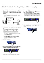
Страница 182: ...UT OFF in advance Power Supply V Digital Multimeter Calibration Circuit 2 Set the constant voltage setting value to xV and the constant current setting value to yA and set the output to ON 30 200 30 4...

Страница 183: ...isplay the setting item number 25 in the Number Display voltage At that time the voltage measured value is displayed in the Number Display current 10 Adjust the CURRENT dial so that the voltage measur...

Страница 184: ...rent setting value to yA and set the output to ON 30 200 30 400 60 100 60 200 xV 1 00V 1 00V 1 00V 1 00V yA 0 1A 0 1A 0 1A 0 1A 500 12 500 24 1000 6 1000 12 xV 1 0V 1 0V 1V 1V yA 0 10A 0 10A 0 010A 0...

Страница 185: ...er 27 in the Number Display voltage At that time the current measured value is displayed in the Number Display current The figure above is an example of connecting HX030 200G4 10 Adjust the CURRENT di...

Страница 186: ...nder Useful Functions page 57 3 Set the constant voltage setting value to xV and the constant current setting value to yA and set the output to ON 30 200 30 400 60 100 60 200 xV 0 00V 0 00V 0 00V 0 00...

Страница 187: ...11 Adjust the CURRENT dial so that the voltage monitor value is the actual output voltage value digital multimeter measurement a 30 200 30 400 60 100 60 200 a 3 3 6 6 500 12 500 24 1000 6 1000 12 a 50...

Страница 188: ...nder Useful Functions page 57 3 Set the constant voltage setting value to xV and the constant current setting value to yA and set the output to ON 30 200 30 400 60 100 60 200 xV 0 00V 0 00V 0 00V 0 00...

Страница 189: ...just the CURRENT dial so that the current monitor value is the actual output current value digital multimeter measurement a 30 200 30 400 60 100 60 200 a 20 40 10 20 500 12 500 24 1000 6 1000 12 a 1 2...

Страница 190: ...system 50 60Hz Rated power 12kVA 23kVA 12kVA 23kVA 12kVA 23kVA 12kVA 23kVA Operating power supply AC342V 440V three phase four wire system 45Hz 65Hz Input Current 1 16A 32A 16A 32A 16A 32A 16A 32A In...

Страница 191: ...20 0A 0 0A 105 0A 0 0A 210 0A 0 00A 12 60A 0 00A 25 20A 0 000A 6 300A 0 00A 12 60A Accuracy 12 0 5 0 1A of set value 0 5 0 2A of set value 0 5 0 05A of set value 0 5 0 1A of set value 0 5 5mA of set v...

Страница 192: ...2digit 2mA of reading 0 5 2digit 20mA of reading Temperature Coefficient Typical Value 200ppm C Power Meter 4 Digit Digital Meter Maximum Display 14 9 999kW 99 99kW 9 999kW 99 99kW 9 999kW 99 99kW 9 9...

Страница 193: ...0 6 5digit 50mA of set value 12 0 6 10digit 100mA of set value 12 0 6 5digit 5mA of set value 12 0 6 5digit 50mA of set value 12 Operation Can select from operations below Output OFF by switching stop...

Страница 194: ...300ms CV Priority Low Speed 500ms CC Priority High Speed 10ms CC Priority Medium Speed 100ms CC Priority Low Speed 200ms CV Priority Low Speed 500ms for standard version model name without F Variable...

Страница 195: ...rve 0 A Curve External Voltage 0 10V DC External Voltage Isolated 0 to 10V DC only for isolation option featured type model name with I Output ON OFF Control Normal Can be controlled at external conta...

Страница 196: ...1000 6 1000 12 Environment Indoor Setting Category and Pollution Degree 2 Environmental Temperature Operation 0 to 50 C Saving 20 C to 70 C Humidity Operation 20 to 90 RH Saving 20 to 90 RH Maximum He...

Страница 197: ...Specifications 197 External Diagrams 1 HX S 030 200G4 F I...

Страница 198: ...Specifications 198 2 HX S 030 400G4 F I...

Страница 199: ...Specifications 199 3 HX S 060 100G4 F I...

Страница 200: ...Specifications 200 4 HX S 060 200G4 F I...

Страница 201: ...Specifications 201 5 HX S 0500 12G4 F I...

Страница 202: ...Specifications 202 6 HX S 0500 24G4 F I...

Страница 203: ...Specifications 203 7 HX S 01000 6G4 F I...

Страница 204: ...Specifications 204 8 HX S 01000 12G4 F I...

Страница 205: ...A 3V 6V 9V 12V 15V 18V 21V 24V 27V 30V 0 5 10 15 20 25 30 0 40 80 120 160 200 240 280 320 360 400 440 A A 3V 6V 9V 12V 15V 18V 21V 24V 27V 30V Input Current A Output Current vs Input Current Output C...

Страница 206: ...30 0 20 40 60 80 100 120 140 160 180 200 220 A A 6V 12V 18V 24V 30V 36V 42V 48V 54V 60V Input Current A Output Current vs Input Current Output Current A Input Current A Output Current vs Input Current...

Страница 207: ...0 0 1 2 2 4 3 6 4 8 6 0 7 2 8 4 9 6 10 8 12 0 13 2 A A 5V 50V 100V 150V 200V 250V 300V 350V 400V 450V 500V Input Current A Output Current vs Input Current Output Current A Input Current A Output Curre...

Страница 208: ...0 0 0 6 1 2 1 8 2 4 3 0 3 6 4 2 4 8 5 4 6 0 6 6 A A 10V 100V 200V 300V 400V 500V 600V 700V 800V 900V 1000V Input Current A Output Current vs Input Current Output Current A Input Current A Output Curre...

Страница 209: ...V 21V 24V 27V 30V 0 10 20 30 40 50 60 70 80 90 100 0 20 40 60 80 100 120 140 160 180 200 220 A 3V 6V 9V 12V 15V 18V 21V 24V 27V 30V Efficiency Output Current vs Efficiency Output Current A Efficiency...

Страница 210: ...10 20 30 40 50 60 70 80 90 100 0 10 20 30 40 50 60 70 80 90 100 110 A 6V 12V 18V 24V 30V 36V 42V 48V 54V 60V Efficiency Output Current vs Efficiency Output Current A Efficiency Output Current vs Effi...

Страница 211: ...0 40 50 60 70 80 90 100 0 2 4 6 8 10 12 14 A 5V 50V 100V 150V 200V 250V 300V 350V 400V 450V 500V Efficiency Output Current vs Efficiency Output Current A Efficiency Output Current vs Efficiency Output...

Страница 212: ...30 40 50 60 70 80 90 100 0 1 2 3 4 5 6 7 A 10V 100V 200V 300V 400V 500V 600V 700V 800V 900V 1000V Efficiency Output Current vs Efficiency Output Current A Efficiency Output Current vs Efficiency Outpu...

Страница 213: ...rrent Wave Form The entire waveform when you enter the AC440V The expansion waveform when you enter the AC440V Output timing for the HOTSTART setting Input Voltage 1 V div Input Current 50A div Input...

Страница 214: ...Specifications 214 Appendix 4 Loaded Current vs Recommended Conductor Area Recommended Sectional Conductor Area mm2 Load Current...

Страница 215: ...ON OFF Rectifier Circuit To each part Insulation Inverter Converter POWER BLOCK P ON GOOD Deteciton Circuit OUT ON Signal TRIP Signal DC OUTPUT S S Current Detection Resistance Constant Current Error...

Страница 216: ...Postal code 213 8558 24 16 Mizonokuchi 1 chome Takatsu ku Kawasaki shi Kanagawa 213 8558 Japan HX S G4 Series Instruction Manual July 2021 Ver3 0 DOC 2008 03...

Отзывы: