20
1).
Use the “
/
” button to switch between the
interlock modes;
“OVERRIDE” mode enables an interpreter in a
booth to override an occupied channel in the
same booth, but supplying the same channel.
“INTERLOCK” mode prevents that two
interpreters engage the same channel in the
same booth.
2).
Use the “MENU” button to confirm selected
interlock mode and go to step f).
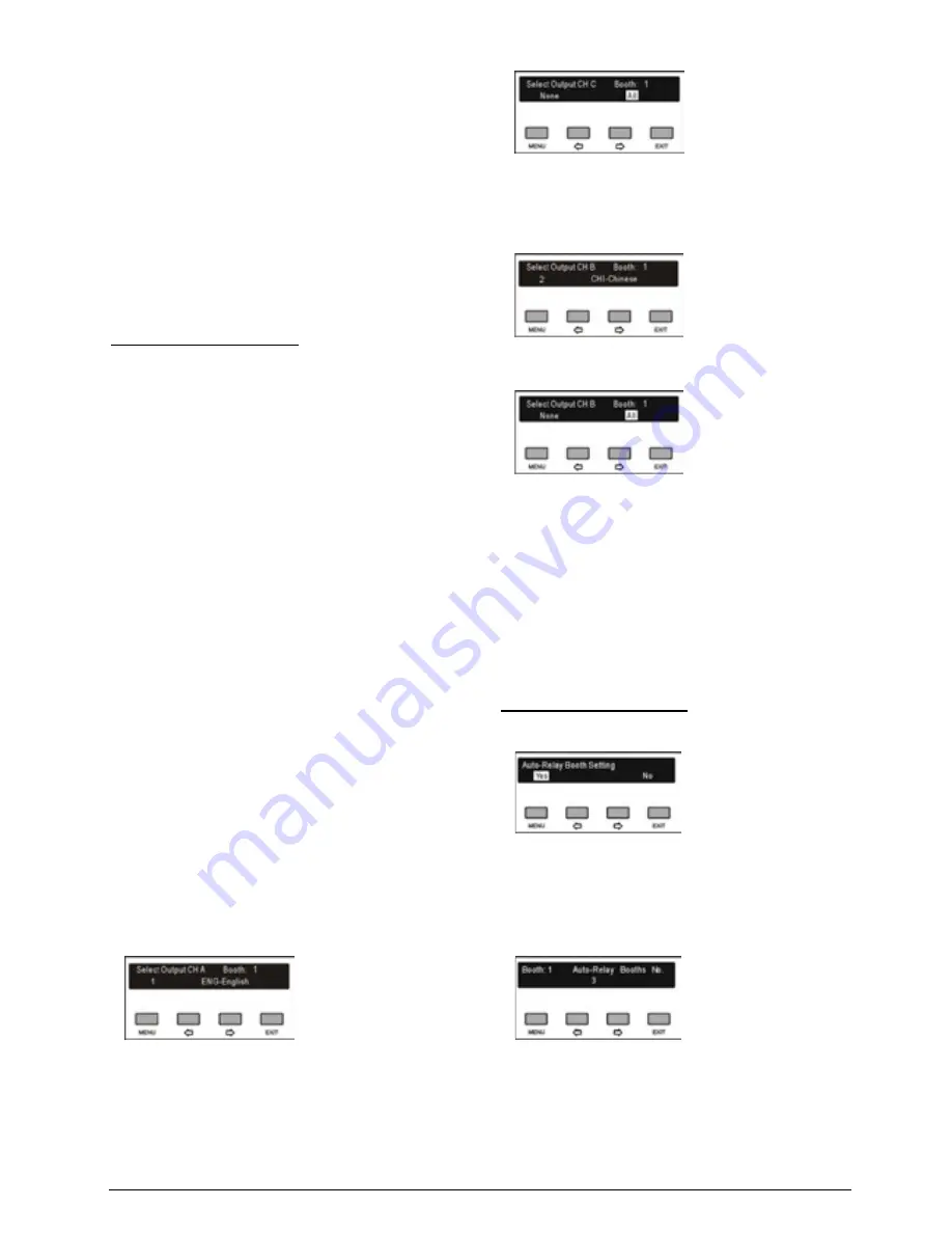
f). Select language for booth
To distribute interpretation languages separately, A/B/C
channels are provided in each interpreter unit. The
language setting of A/B/C channels for all interpreter
units in one booth is uniform. After setup of booth
numbers, the user interface to setup output channel
A/B/C language will show for each booth.
General procedure:
1
st
step:
select a language for channel A
2
nd
step:
select ALL or NONE for channel C
If ALL is selected for C then
3
rd
step
: select a language for B. Three channels are
now available: A and B output a selected language and
C outputs any available language.
If NONE is selected for C then
4
th
step:
select B: NONE or ALL
If NONE is selected for B, only A outputs the selected
language of the 1
st
step. B and C do not output
languages;
If ALL is selected for B, then 2 output channels are
available: A outputs the selected language of the 1
st
step and B outputs any available language. No
language output at C.
1).
Setup channel A language for booth 1: press the
“
/
” button to select language from those
languages that have been selected in step b)
and press the “MENU” button to confirm;
2).
Select channel C language for booth 1: “NONE”
or “ALL”;
3).
If ALL is selected for C then press the “
/
”
button to select language for B from those
languages that have been selected in step b)
and press the “MENU” button to confirm;
4).
If NONE is selected for C then select channel B
language from “NONE” or “ALL”;
“
NONE
” stands for no language output from
channel B;
“
ALL
” stands for the language of channel B
which can be any of the selected languages.
Press the “MENU” button to confirm and go to
configuration for next booth;
5).
Repeat 1) - 2) to setup output channel A/B/C
language for all booths and go to step g).
g). Auto-Relay booth Setting
Setup Auto-Relay booth.
1)
. Press the “
/
” button to select yes or no
If select “
No
”, press the menu button to
confirm;
If select “
Yes
”, press the “MENU” button to
confirm and go to next step;
2)
. Press the “
/
” button to select auto-relay booth
quantity and press the “MENU” button to go to the
next step;
Содержание HCS-4100MA/50
Страница 50: ...35 Figure 2 1 10 Floor mode setting Normal Mode Figure 2 1 11 Floor mode setting Insert Mode...
Страница 51: ...36 Figure 2 1 12 Floor mode setting Sync Line Out1 Mixer...
Страница 67: ...52 Figure 3 2 6 Installation diagram of HCS 48U6SPK...
Страница 79: ...64 3 3 2 Installation 3 3 2 1 Cutout Figure 3 3 2 Cutout of HCS 48U7 series flush mounted congress unit unit mm...
Страница 80: ...65 Figure 3 3 3 Cutout of HCS 48U8 series flush mounted congress unit unit mm...
Страница 81: ...66 Figure 3 3 4 Cutout of HCS 48U9 series flush mounted congress unit unit mm...
Страница 82: ...67 Figure 3 3 5 Cutout of HCS 48U7MICSPK flush mounted congress unit unit mm...
Страница 83: ...68 3 3 2 2 Installation Figure 3 3 6 Installation of HCS 48U7 series flush mounted congress unit...
Страница 84: ...69 Figure 3 3 7 Installation of HCS 48U8 series and HCS 48U9 series flush mounted congress unit...
Страница 85: ...70 Figure 3 3 8 Installation of HCS 48U7MICSPK series flush mounted congress unit...
Страница 87: ...72 Figure 3 3 11 Disassembly caution of HCS 48U8 and HCS 48U9 series flush mounted congress unit...
Страница 100: ...85 3 4 2 Installation Figure 3 4 2 Cutout of HCS 48U10 series congress unit unit mm...
Страница 101: ...86 Figure 3 4 3 Installation of HCS 48U10 series congress unit...
Страница 162: ...147 3 10 2 Installation Figure 3 3 2 Installation of HCS 4851 50 series congress unit unit mm...
Страница 163: ...148 Figure 3 3 3 Installation of HCS 4851 50 series congress unit...
Страница 181: ...166 Figure 3 12 3 Installation of HCS 4325U 50 congress unit unit mm...
Страница 196: ...181 Figure 3 13 7 Multi function connector connected to the HCS 4341 50 series congress unit...
Страница 212: ...197 Figure 3 14 18 Multi function connector connected to HCS 4841 42 43 series congress units...
Страница 225: ...210 3 16 2 Installation Figure 3 16 2 Installation of HCS 1080 electronic nameplate...
Страница 230: ...215 4 1 HCS 4385U 50 4 1 1 Functions and indications Front Side Bottom Figure 4 1 1 HCS 4385U 50 Interpreter unit...
Страница 243: ...228 4 2 HCS 8385 60 4 2 1 Functions and indications Front Side Bottom Figure 4 2 1 HCS 8385 60 Interpreter unit...
Страница 275: ...260 HCS 1020 clip microphone...
Страница 316: ...301 Appendix Custom made cable Appendix Dedicated 6 PIN Extension Cable...


