114
3.6.3.2 Chairman unit
The chairman unit features all the functions of a
delegate unit, and the following additional functions:
1. Priority
If the priority mode on the main unit is configured
as “All mute”, all active delegate microphones
(except VIP units) will be muted temporarily when
this key is pressed and they will restore when this
key is released;
If the priority mode on the main unit is configured
as “All off”, all active delegate microphones (except
VIP units)
will be turned off and the
request-to-speak list will be purged (under “Open”
and “Apply” mode) when this key is pressed.
2. Speaking
If the active microphone capacity is not full, the
chairman can activate his/her microphone normally,
the operation is the same as for the delegate unit.
If the active microphone capacity is full, the
chairman cannot activate his/her microphone. But
he/she can use the priority key to “All mute” or “All
off” other delegate microphones and give his/her
speech.
3. Controlling delegate unit
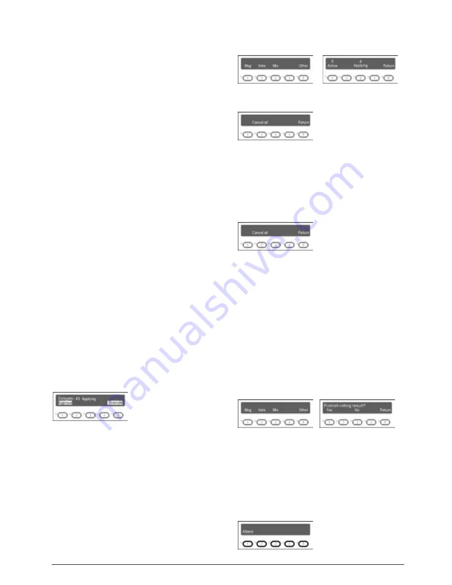
A. Approve delegate unit’s request to speak
Without PC and under “Apply” mode, when a delegate
requests to speak, a ring tone will be emitted by the
built-in loudspeaker in the chairman’s unit.
The chairman can now approve delegate’s request and
activate delegate’s microphone by pressing key “1” or
reject delegate’s request by pressing key “5”.
At most 6 microphones (default) can request at the
same time. When a request is approved, the last
activated microphone will be turn off at the same time.
B. Turn off delegate microphone or reject delegate
unit’s request to speak
The initial interface of the chairman unit is shown in the
following figure at the left side. Press “Microphone”
(key “3”) to go to the microphone status interface as in
the following figure at the right side:
Press “
Active
” (key “1”) to go to the active
microphone control interface:
If any delegate’s microphone is active, “Cancel all”
(key “2”) will be available and the chairman can
press this key to deactivate all active delegate’s
microphone.
Press “
Applying
” (key “3”) to control the “request to
speak” interface:
If connected to the PC, “Cancel all” (key “2”) will be
available and the chairman can press this key to
reject all requests (refer to application software
user’s manual).
4. Voting
A. Without PC
HCS-4380SCW/50 chairman unit can originate voting
without a PC:
a. In the initial interface of the chairman unit, press
“Vote” (key “2”) to go to the voting control interface as
shown in the following figure at the right side:
b. If “Yes” (key “1”) is selected, the voting results will be
displayed on the LCDs of all congress units; if “No”
(key “3”) is selected, the voting results will be
displayed only on the LCD of the chairman unit. After
selection, the sign-in indicating light of all congress
units will blink. The delegates can press key “1” to
sign-in. After sign-in, the voting indicating lights will
blink, the delegate is now enabled to vote:
Содержание HCS-4100MA/50
Страница 50: ...35 Figure 2 1 10 Floor mode setting Normal Mode Figure 2 1 11 Floor mode setting Insert Mode...
Страница 51: ...36 Figure 2 1 12 Floor mode setting Sync Line Out1 Mixer...
Страница 67: ...52 Figure 3 2 6 Installation diagram of HCS 48U6SPK...
Страница 79: ...64 3 3 2 Installation 3 3 2 1 Cutout Figure 3 3 2 Cutout of HCS 48U7 series flush mounted congress unit unit mm...
Страница 80: ...65 Figure 3 3 3 Cutout of HCS 48U8 series flush mounted congress unit unit mm...
Страница 81: ...66 Figure 3 3 4 Cutout of HCS 48U9 series flush mounted congress unit unit mm...
Страница 82: ...67 Figure 3 3 5 Cutout of HCS 48U7MICSPK flush mounted congress unit unit mm...
Страница 83: ...68 3 3 2 2 Installation Figure 3 3 6 Installation of HCS 48U7 series flush mounted congress unit...
Страница 84: ...69 Figure 3 3 7 Installation of HCS 48U8 series and HCS 48U9 series flush mounted congress unit...
Страница 85: ...70 Figure 3 3 8 Installation of HCS 48U7MICSPK series flush mounted congress unit...
Страница 87: ...72 Figure 3 3 11 Disassembly caution of HCS 48U8 and HCS 48U9 series flush mounted congress unit...
Страница 100: ...85 3 4 2 Installation Figure 3 4 2 Cutout of HCS 48U10 series congress unit unit mm...
Страница 101: ...86 Figure 3 4 3 Installation of HCS 48U10 series congress unit...
Страница 162: ...147 3 10 2 Installation Figure 3 3 2 Installation of HCS 4851 50 series congress unit unit mm...
Страница 163: ...148 Figure 3 3 3 Installation of HCS 4851 50 series congress unit...
Страница 181: ...166 Figure 3 12 3 Installation of HCS 4325U 50 congress unit unit mm...
Страница 196: ...181 Figure 3 13 7 Multi function connector connected to the HCS 4341 50 series congress unit...
Страница 212: ...197 Figure 3 14 18 Multi function connector connected to HCS 4841 42 43 series congress units...
Страница 225: ...210 3 16 2 Installation Figure 3 16 2 Installation of HCS 1080 electronic nameplate...
Страница 230: ...215 4 1 HCS 4385U 50 4 1 1 Functions and indications Front Side Bottom Figure 4 1 1 HCS 4385U 50 Interpreter unit...
Страница 243: ...228 4 2 HCS 8385 60 4 2 1 Functions and indications Front Side Bottom Figure 4 2 1 HCS 8385 60 Interpreter unit...
Страница 275: ...260 HCS 1020 clip microphone...
Страница 316: ...301 Appendix Custom made cable Appendix Dedicated 6 PIN Extension Cable...


