


Sentinel Pro Installation Procedure and Reference Manual
- for Coral IPx / FlexiCom
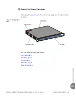
About the Coral Sentinel Pro
15
Sentin
el
Pro Exterior Description
2
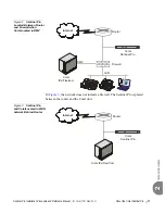
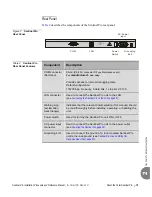
Rear Panel
describes the components of the Sentinel Pro rear panel.
Figure 7
Sentinel Pro
Rear Panel
Table 4
Sentinel Pro
Rear Panel Features
z
ON
OFF
COM
INPUT:
100 - 240Vac 0.1A
50/60Hz
GND
Grounding
Bolt
AC Power
Input
Power
Switch
LAN
COM
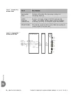
Component
Description
COM connector
(Not Used)
DA-9S (RS-232) connector D-Type Maintenance port.
For
manufacturer’s
use, only.
Provides access to internal debugging tools.
Default configuration:
115200 bps, No parity, 8 data bits, 1 stop bit, VT-100.
LAN connector
Used to connect the Sentinel Pro unit to the LAN
(see
Connecting the Sentinel Pro to the LAN
).
Warning sign
(exclamation
mark triangle)
Indicates that the relevant documentation (this manual) should
be read thoroughly before installing, operating, or handling the
unit.
Power switch
Used for turning the Sentinel Pro unit ON or OFF.
AC power input
connector
Used to connect the Sentinel Pro unit to the power outlet
(see
Grounding bolt
Used to connect the ground of a rack-mounted Sentinel Pro
unit to the rack ground (see
Sentinel Pro Ground Wiring (for
).
Содержание Coral Sentinel Pro
Страница 1: ...Coral Sentinel Pro Installation Procedure and Reference Manual Version 6 78 Document Edition 3 2...
Страница 56: ...NOTES...
Страница 62: ...NOTES...
Страница 70: ...NOTES...
Страница 71: ......
Страница 72: ......