Y-4
Y-4
Air Bleeding Procedure
26
WY05-4181E
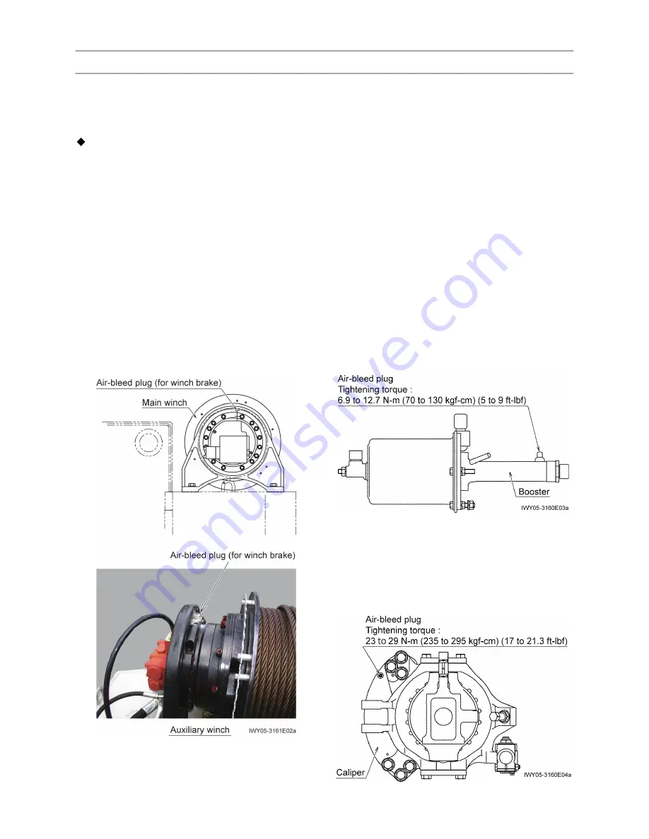
2. Winch brake
[NOTICE]
Bleed the main and auxiliary winch circuits by
following the procedures below. The procedures are
common to the both circuits.
1. Engine speed: idling (700 min
-1
)
2. Lever operation: Operate the lever by inching
operation within the range that the drum can fun.
Operate the lever so that the working pressure
does not exceed the value described below.
2.5 MPa (25.5 kgf/cm
2
) (360 psi)
(during hoisting up)
4.5 MPa (45.9 kgf/cm
2
) (650 psi)
(during hoisting down)
3. Bleeding will be completed when the oil flowing
out of the air-bleed plug hole contains no bubbles.
3. Service brake
[NOTICE]
The vehicle has two boosters; one for the front
wheel brakes and the other for the rear wheel
brakes.
Take care of spattering the brake fluid and the fluid
level in the fluid reservoir while bleeding.
1. With the sufficient compressed air in the air
reservoir, depress the brake pedal and loosen the
air-bleed plug on the booster to bleed the circuit.
2. Then tighten the air-bleed plug before releasing
the brake pedal.
3. Repeat the above steps until the flowing brake
fluid contains no air bubbles. After the air bubbles
go out, tighten the air-bleed plug while letting the
fluid flow out.
[NOTICE]
The vehicle has each two air-bleed plugs for the
front axle and two for the rear axle.
4. Bleed the wheel cylinders in the calipers of the
axles in the steps same as above.
Содержание GR-300EX-3
Страница 1: ......
Страница 8: ...7 WA04 4880E 6 Group index System Diagrams Data Adjustment and Checks Y Z Y Z...
Страница 27: ...14 WY02 1792E Y 2 Y 2 Adjusting Pressure Hydraulic Pressure...
Страница 97: ...Z 6 Z 6 Hydraulic Parts Location Diagram Upper 26 WZ07 3762E 5 Return 6 Drain 3 343 458 62000 1 343 465 03000...
Страница 98: ...Z 6 Z 6 Hydraulic Parts Location Diagram Upper 27 WZ07 3762E 7 Gauge 3 343 450 35500...
Страница 99: ...Z 6 Z 6 Hydraulic Parts Location Diagram Upper 28 WZ07 3762E 8 Pilot 0 343 458 63000...
Страница 108: ...37 WZ08 0620E Z 9 Z 9 Pneumatic Parts Location Diagram 3 Control parts lower 1 349 233 11000 0 349 233 10000...


