PKIR, PKIS
| PP-28_201612 | 33 / 48
Tf
Tf
LED
BAT
S1 S2 S3 S4 S5 S6
<5°
<80°
2
1
N L1
AC 230 V, open - close
Tf
Tf
LED
BAT
S1 S2 S3 S4 S5 S6
<5°
<80°
2
1
–
+
T
~
AC/DC 24 V, open - close
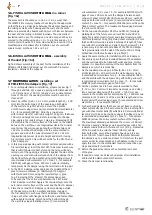
Fig. 24: Actuator BELIMO BFL24-T and BFN24-T connection
scheme for DV9-T
Notes:
•
Connection via safety isolating transformer.
•
Parallel connection of other actuators possible. Observe the
performance data.
•
Combination of power supply voltage and safety extra-low
voltage not permitted at the both auxiliary switches
Fig. 23: Actuator BELIMO BFL230-T and BFN230-T connection
scheme for DV7-T
Notes:
•
Caution: Power supply voltage!
•
The actuator must be protected by a fuse that does not exceed 6 A.
•
Parallel connection of other actuators possible. Observe the
performance data.
•
Combination of power supply voltage and safety extra-low
voltage not permitted at both auxiliary switches.
1
blue
2
brown
S1
violet
S2
red
S3
white
S4
orange
S5
pink
S6
grey
Tf
Thermal fuse
Cables colours
1
black
2
red
S1
violet
S2
red
S3
white
S4
orange
S5
pink
S6
grey
Tf
Thermal fuse
Cables colours
Legend
DC
Direct current
AC
Alternating current
230
Servomotor 230 V
24
Servomotor 24 V
T
Thermoelectric fuse
ST
Supply and communication unit BKN230-24
W
Cables for the supply and communication unit
SR
Modulated servomotor with the control 0 V - 10 V
1
Open
2
Closed
3
Closed by impulse in the circuit
4
Closed after interruption of the circuit
U
Source voltage as per Tab. 27
E
Electromagnet as per Tab. 27
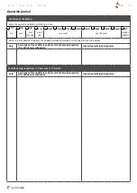
Fig. 25: Connection of the electromagnets and end switches according to Tab. 26
Electromagnet
impulse connection
Electromagnet
interruption connection
1
3
U
E
4
1
U
E
1
2
U
2
1
U
Indication closed
Indication open


