PKIR, PKIS
| PP-28_201612 | 37 / 48
1.1 WET
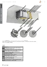
INSTALLATION EI120S - using plaster mix-
ture, mortar or concrete (Fig. 5, 6)
This installation can be used for fire dampers as per Tab.1 and 2.
1. For installation of a round damper, prepare a round opening of
diameter
DN
+ 80 mm, for a rectangular damper a rectangular
opening with dimensions
W
+ 120 mm and
H
+ 120 mm (as
per Fig. 1 through 4 and Tab. 5 and 7), the opening surfaces
must be even and cleaned off. The flexible wall opening must
be reinforced as per the standards for plasterboard walls.
2. Insert the closed damper into the middle of the opening so
that the damper blade is in the wall. Use the bendable hanger
(1; or hangers, if there are two of them) to secure the dam-
per against the wall using a suitable screw (3; recommended
screw diameter 5,5 - for example DIN7981).
3. Fill in the area between the wall and the damper with plaster
mixture, mortar or concrete (2), while paying attention to
prevent fouling of the damper’s functional parts, which could
limit its correct functionality. The best way is to cover the
functional parts during installation. The seepage of the filling
material can be prevented by using the supplied PRR-PKI /
PRS-PKI coverplates. However, these are not required for wet
installation.
First let the plaster mixture or mortar or concrete harden
and then perform the next steps!
4. If needed, uncover and clean the damper after installation.
5. Check the damper functionality
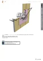
1.2 DRY
INSTALLATION EI90S - using mineral wool
and coverplates (Fig. 7, 8)
This installation can be used for fire dampers as per Tab.1 and 2.
1. For installation of a round damper, prepare a round opening of
diameter
DN
+ 120 mm, for a rectangular damper a rectangular
opening with dimensions
W
+ 120 mm and
H
+ 120 mm (as
per Fig. 1 through 4 and Tab. 9 and 11), the opening surfaces
must be even and cleaned off. The flexible wall opening must
be reinforced as per the standards for plasterboard walls.
2. (Applies only to PKIS-EI90S)
Insert the closed damper into the middle of the opening so
that the damper blade is in the wall. Use the bendable hanger
(1) to secure the damper against the wall using a suitable
screw (3; recommended screw diameter 5,5 - for example
DIN7981).
3. (Applies only to PKIS-EI90S)
From the hanger (hangers) side close the gap between the
damper and the mounting opening for the round damper
using PRR-PKI or PRS-PKI coverplates (4), for the rectangular
damper with PRS-PKI coverplates using screws (3) through
pre-drilled holes.
4. (Applies only to PKIS3G and PKIR3G)
With these dampers it is necessary to install the bendable
hangers (1) onto the coverplates using suitable screws (3;
recommended screw diameter 5,5 - for example DIN7981).
Therefore it is necessary to begin by installing the two neigh-
boring PRR-PKI or PRS-PKI coverplates (4) from the mecha-
nism side and secure them against the wall in such way that
the damper can be passed through them into the opening
and secure both the coverplates and the damper into the wall
using suitable screws (3; recommended screw diameter 5,5
- for example DIN 7981). Subsequently mount the remaining
coverplates from the mechanism side.
5. Fill in the area between the wall and the damper with mineral
wool (2) with density at least 50 kg/m
3
thoroughly but in
such way that will not deform the damper housing, while
paying attention to prevent fouling of the damper’s functional
parts, which could limit its correct functionality.
6. Close the gap between the damper and the mounting
opening, for a round damper use PRR-PKI coverplates, for a
rectangular damper use PRS-PKI coverplates with screws (5)
through pre-drilled holes.
7. All the gaps between the coverplates, between coverpla-
tes and the wall, between coverplates and the fire damper
need to be filled with fire resistant mastic (e.g. Promaseal-
A/fa. Promat).
8. If needed, clean the damper after installation.
9. Check the damper functionality (see the operation manual).
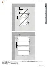
1.3
INSTALLATION INTO A
SOFT CROSSING
EI90S
(Fig. 9, 10)
This installation can be used for fire dampers as per Tab.1 and 2.
1. For installation of a round damper prepare a round opening of
diameter
DN
+ 120 mm, for a rectangular damper a rectangular
opening with dimensions
W
+ 120 mm and
H
+ 120 mm (as
per Fig. 1 through 4 and Tab. 13 and 15), the opening surfaces
must be even and cleaned off. The flexible wall opening must
be reinforced as per the standards for plasterboard walls.
2. Prepare mineral wool installation segments (2 with cubic
weight 150 kg/m
3
, thickness 100 mm). First apply a suitable
fireproof layer/glue (e.g. Promastop-CC/fa. Promat)
onto the damper at the place of its future placement,
assemble and glue the filling of the future installation
with the same glue. After the glue has dried the damper
along with the filling are ready for installation.
3. Apply the same glue onto the internal surface of the wall
opening. Also apply the same glue on the external surface
of the filling glued on the damper surface. Immediately after
application place the damper into the wall opening in such
way that will not deform the damper housing.
The damper blade must be located in the supporting struc-
ture. Then fix the damper using the bendable bracket.
4. After inserting the damper into the opening and fixing it
using the bendable brackets (they determine the depth
of the damper’s placement into the wall) and suitable
screws (3; recommended screw diameter 5,5 - for example
DIN7981), apply the same fire resistant mastic (4), at least
2mm thick and 100 mm wide, on the opening filling and wall
edges evenly from both sides (adjacent duct must be covered
with the mastic too). Do not apply this layer in the place
where the mechanism is located, inspection openings and
manufacturer labels.
5. (Applies only to PKIS-EI90S)
It is necessary to fix the dampers installed into a wall using
four steel L-profiles (5; 60
×
40
×
3 mm) from above and
below. Anchor the profiles to the wall on each end using at
least one screw (6; recommended screw diameter 5,5 - for
example DIN7981) and self-drilling screws against the dam-
per with maximum 200 mm gaps (7; recommended screw
diameter 3,9
×
max.13 - for example DIN7504).
6. Dampers installed into a ceiling need to be fixed onto
the ceiling using two steel L-profiles (5; 60
×
40
×
3 mm)
from above (applies for all types). Anchor the profiles to the
ceiling on each end using at least one screw (6; recommen-
ded screw diameter 5,5 - for example DIN7981) and self-
drilling screws against
the damper with maximum 200 mm gaps (7; recommended
screw diameter 3,9
×
max.13 - for example DIN7504).
7. Before the glue dries, remove the unwanted remnants
of the glue.
8. If needed, uncover and clean the damper after installation.
9. Check the damper functionality.


