65
7
SYSTEMA S.p.A.
INFRA ES rev. 02GBEN13112018
FINAL TESTING
7.5 POSSIBLE AIR DAMPER ADJUSTMENT
All Systema products are configured and checked at the factory before shipment.
The appropriate standard air damper setting is also performed at the factory and
correct operation of the burner is checked.
It is usually not necessary to make any adjustments to the burner air damper, however, there may be special
cases where the performance level (paragraph 7.4 at page 63) given by the combustion analysis does not
reflect the plate values or the values given in table 7.1 on page 62.
In these rare cases, further adjustment of the air damper must be made so that the performance values given
by the combustion analysis reflect those in data plate or the values given in table 7.1, page 62.
To adjust the air damper, proceed as follows:
1) Make sure that the burner is off and then discon
-
nect it electrically;
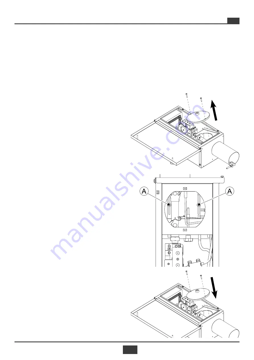
2) Remove the screws and cover of the combustion
chamber (fig. 7.5);
3) loosen the screws (A) in fig. 7.6;
4) rest the cover and tighten the screws (fig. 7.7);
5) adjust the combustion air damper, as indicated in
the following paragraph 7.5.1;
6) at the end of the adjustment, reopen the cover
and fasten the two screws (A) of fig. 7.6;
7) close the cover and tighten the screws (Fig. 7.7).
The standard settings are shown in tab. 7.2 on page
66, a notch (point
C
, Fig. 7.9) is shown on the damp
-
er to be aligned with the graduated scale (3, 9, 27,
78) as a reference for the position.
Furthermore, as a further reference, it is possible to
check alignment of the hole (
B
) on the damper with
the holes (
D
) positioned below
Fig. 7.5
Fig. 7.6
Fig. 7.7


