8
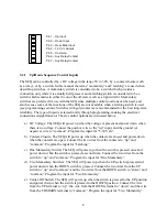
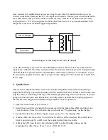
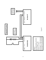
relay contacts for confirmation and you are using the aux relay for another function you can
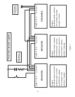
connect a small relay between the 12V dc output and common. The relay coil current must not be
more than 40mA, and you must connect a diode such as a 1N4148 or 1N4002 across the relay
coil (cathode to +12V dc) to suppress the back EMF from the coil. If you need assistance with
this please contact our technical support department.
Connecting a 12 volt relay to the 12V dc output
To use the auxiliary relay contacts for confirmation, connect the two aux relay contacts to the
input of the controller. The relay contacts will be closed when all banks are powered up and open
when all banks are powered down. The default for menu item “Aux Sync” is “Confirm” so you
do not need to program this item unless you previously changed it. The contacts are rated at 30V
dc at 1 amp.
4
Quick Start
This section is intended to allow users with a simple straightforward system incorporating a
single SX2120-SEQ to get up and running with the minimum of effort. If this is not the case then
skip this entire section and go directly to the detailed programming section (section 5). If you are
going to follow the quick start instructions, you only need to perform the following steps since
the unit has been shipped with default settings suitable for basic operation.
1.
Make all connections as per section 3.
2.
Insert the screwdriver provided in the accessory kit in the hole labeled SEL and turn it one
click clockwise. Press the red button and you should see “Programming” on the display.
3.
Set the first item “Up & Down Inputs” as per section 3.2.1 by rotating ADJ.
4.
Advance SEL one more click. You will now be able to set the first delay time which is for
bank A powering up. Use ADJ to set the required delay time in seconds.
5.
Advancing SEL one click at a time and using ADJ to adjust the delay times, set the
remaining five delay times: B on, C on, A off, B off, C off.
12V dc Output
Common


