16
6.1.5
Other Functions
Reading through the programming section is a good way to understand all the functions and
options available in the SEQ. Most of the functions are associated with main operation outlined
in this section above. However, there are some other independent functions that can be selected:
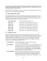
The front panel button can be programmed to be operational, non-operational or operate after a
one-second delay. Choosing the last setting prevents accidental power-up or power-down. See
section 5.5 for more details.
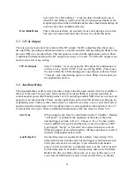
The SEQ has built-in voltage limits that will cause the unit to power down if the line voltage is
outside these limits. The low limit can be set from 90V to 110V and the high limit can be set
from 130V to 150V. See section 5.6 for more details.
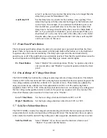
The SEQ has internal self-test circuitry that constantly monitors the operation of the unit and
displays the word “Good” or “Fail” on the front panel. The unit can be programmed to shut down
in the unlikely event that the self-test should fail. See section 5.7 for more details.
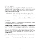
There are two “Restore” options. The first option allows the unit to restore to a power-on state
after loss of AC power or out-of-range AC voltage. The second option allows the unit to restore
to a power-on state after being forced off by an over-ride. See section 5.8 for more details.
6.2
Single Unit System
Most of the information necessary to install and set up a single unit system can be found in
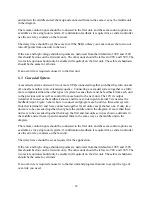
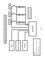
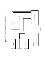
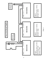
sections 3.2 and 6.1. Figure 1 shows a single unit system controlled by momentary switches at
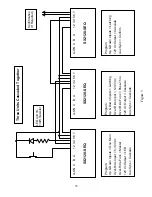
three different locations, and figure 2 shows a single unit controlled by a central controller.
6.3
Expanded System
An expanded system consists of an SEQ in combination with a remote turn-on SurgeX such as
the SX1120-RT or the SX20-NE/RT. Such a system provides a total of four banks and 40 Amps
total load capacity. The auxiliary relay inside the SEQ is used to control the second unit. An
expanded system can be controlled by the same inputs as a single unit system. The only
difference in remote control connections is that, because the aux relay is used to control a second
unit it cannot be used for confirmation feedback to a central controller. In this case, the 12V dc
output can be used for confirmation by programming it to Confirm rather than LED, or the aux
relay contacts on the RT unit can be used.
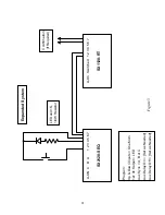
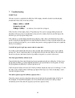
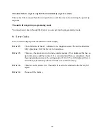
Figure 3 shows how the two units are wired together. The aux relay contacts on the SEQ
(terminals 6 & 7) are connected to the contact closure inputs at the back of the RT (terminals 1 &
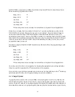
2). In order to work as a 4-bank system the aux relay must be programmed accordingly. The Aux
Sync menu item must be set to A, B or C. This synchronizes the aux relay to one of the internal
triggers used for main banks A, B or C. The Aux Delay On and Aux Delay Off delay times are
then set to position the 4
th
bank wherever it is required to be in the sequence. As an example: if

