background image

7

f)


Latching Switch: The SEQ will power up when the switch is closed and power down
when the switch is open. Connect the two wires from the switch to “up” and “common”.
Program the input for “Latching”.

Note: The front panel button will not operate with options a, b or f

3.2.2


Over-Ride Input

The SX2120-SEQ has the option of adding an over-ride function for purposes such as providing
fire safety over-ride to force the system either on or off. An over-ride is initiated by applying a
dc voltage of 5-30V or by a sustained contact closure. The selection of dc voltage or contact
closure is accomplished during programming. This topic is covered fully in the programming
section.

Connect the over-ride signal to the “over-ride” input and “common”. In the case of a dc voltage,
connect the positive wire to “over-ride” and the negative wire to “common”.

3.2.3


External LED Connections

The SX2120-SEQ is able to drive external LEDs or other signaling devices through its 12V dc
output which can provide up to 40mA of current. External LEDs connected in this way will
mimic the red LED on the front panel. When connecting LEDs to the 12V output, a series
resistor is required. For example, many LEDs work well with 10mA of current, so a 1K resistor
is usually a good choice. If more than one LED is required, then use a separate series resistor for
each LED. In this example, four external LEDs could be powered at 10mA each from one SEQ.
If more than four LEDs are required, it will be necessary to increase the series resistor so that the
total load is not more than 40mA.

Connect each LED anode to “12V dc output” through a resistor, and the cathodes to “common”.

Program the 12V dc Output for “LED”. This causes LEDs connected to the SEQ to flash while
the unit is powering up or powering down in the same manner as the front panel LED.

3.2.4


Confirmation Connection

The SX2120-SEQ offers two ways to provide confirmation feedback to a central controller: a
12V dc output and a pair of isolated relay contacts. Confirmation tells the controller that the SEQ
has indeed powered up or that it is fully powered down. If the 12V dc output and the aux relay
contacts are not used for any other function, you will be free to choose whichever provides the
best interface for the application. However, if one of these outputs is used for another function
you will have to use the one that is available.

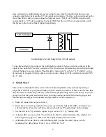
To use the 12V dc output for confirmation, connect “12V dc output” to the positive input of the
controller and “common” to ground. The output will be at 12V when all banks are powered up
and will be zero when all banks are powered down. Program 12V dc Output for “Confirm”. Note
that the SEQ common terminal is shared between the inputs and the 12V dc output. If you need

Содержание SX2120-SEQ

Страница 1: ...SX2120 SEQ USER MANUAL Software Version 1 1 Three Bank Sequencer With Power Conditioning Surge Protection...

Страница 2: ...CONTROL 10 5 2 OVER RIDE CONTROL 10 5 3 12V DC OUTPUT 11 5 4 AUXILIARY RELAY 11 5 5 FRONT PANEL PUSH BUTTON 12 5 6 OUT OF RANGE AC VOLTAGE SHUT DOWN 12 5 7 SELF TEST FAILURE SHUT DOWN 12 5 8 RESTORE F...

Страница 3: ...3 7 TROUBLESHOOTING 24 8 ERROR CODES 25 9 SPECIFICATIONS 26...

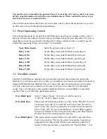
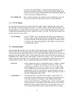
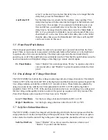
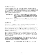
Страница 4: ...ve the button indicates the status of the unit When the red LED is off the unit is fully powered down when it is on the unit is fully powered up when it is flashing the unit is in the process of power...

Страница 5: ...plugging the cord into a 120V ac 20 amp receptacle The SEQ cannot be plugged into a 15 amp receptacle If a 120V 20 amp branch circuit is not available you will need to have one installed by a license...

Страница 6: ...e wire to the up input and the ground or negative wire to common Program the input for 5 30 V dc b Contact Closure The SEQ will power up when the contacts are closed and power down when the contacts a...

Страница 7: ...n one LED is required then use a separate series resistor for each LED In this example four external LEDs could be powered at 10mA each from one SEQ If more than four LEDs are required it will be nece...

Страница 8: ...is section is intended to allow users with a simple straightforward system incorporating a single SX2120 SEQ to get up and running with the minimum of effort If this is not the case then skip this ent...

Страница 9: ...cer and has 21 menu items that control its operation Some menu items allow predetermined options to be selected and others allow time delays or voltage limits to be adjusted All adjustments are made v...

Страница 10: ...C powering off 5 2 Over Ride Control The SX2120 SEQ has an optional over ride and there are four menu items that control this function If you do not require an over ride you can skip the next four me...

Страница 11: ...t The aux relay can be used to provide feedback to a central controller to control another power distribution product or for controlling another SEQ when two or more are ganged or cascaded together Pl...

Страница 12: ...Fr Panel Button Select Enable for normal operation Delay to operate only after a one second delay and Disable to prevent operation from the front panel 5 6 Out of Range AC Voltage Shut Down The SX212...

Страница 13: ...uthorized access to the programming mode From one to six letters A through Z can be used as a password It is important to remember the password because once it has been set you cannot get into the pro...

Страница 14: ...ted in parallel so that the SEQ can be controlled from multiple locations A single push switch would cause the unit to power up on the first press and then power down on the second press A dual moment...

Страница 15: ...that can be used for fire safety and other applications where the power must be held on or forced off The over ride function is programmable so that it can be set to either force the unit off or forc...

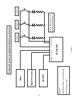
Страница 16: ...ost of the information necessary to install and set up a single unit system can be found in sections 3 2 and 6 1 Figure 1 shows a single unit system controlled by momentary switches at three different...

Страница 17: ...then 5 seconds later bank C turns off In another example if the SX1120 RT should turn on first and off last the programming would be as follows Delay A On 5 Delay A Off 5 Aux Sync A Aux Delay On 0 Aux...

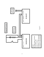
Страница 18: ...unit as well as control from each unit to the next unit The 12V dc output terminal 4 is used as the feedback source and the over ride input terminal 3 is used as the feedback input Figure 5 shows how...

Страница 19: ...SEQ Single Unit System Controlled by Momentary Switches Location 3 Location 2 Location 1 Mixer Signal Processing Amplifier Use an LED and 1K W resistor at each location Program Up Down Inputs One Mom...

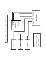
Страница 20: ...5 6 7 SX2120 SEQ Mixer Signal Processing Amplifier Single Unit System Controlled by Central Controller Program Up Down Inputs Latching Aux Sync Confirm Confirmation Feedback Controller Low Voltage Con...

Страница 21: ...5 6 7 SX2120 SEQ A On Switched 1 2 3 4 5 6 7 SX1120 RT LED and 1K 1 4W Resistor Confirmation If Required Program Up Down Inputs One Mom 12v dc Output LED Aux Sync A B or C Aux Delay On Set as Needed...

Страница 22: ...1 2 3 4 5 6 7 SX2120 SEQ A ON C B A 1 2 3 4 5 6 7 SX2120 SEQ Program Up Down Inputs One Mom 12V dc Output LED Aux Sync Gang Confirmation If Required Program Up Down Inputs Latching Aux Sync Gang Progr...

Страница 23: ...n If Required LED and 1K 1 4W Resistor Program Up Down Inputs One Mom Over Ride Input 5 30 Vdc Over Ride Func Master 12V dc Output LED Aux Sync Cascade Program Up Down Inputs Latching Over Ride Input...

Страница 24: ...ion If you have performed initial checks as above and the unit will still not power up it could be because the down input terminal 2 is being held active all the time Remove the terminal block from th...

Страница 25: ...05 The calibration of the AC voltmeter is no longer accurate The unit is otherwise fully operational Call the factory for assistance Error 15 There is a checksum error in the non volatile memory This...

Страница 26: ...ad 3dB 5KHz 26dB 100KHz 38 dB 300KHz 50dB 5MHz 50dB 30MHz Let Through Slew Rate 28V us within the AC power wave envelope less than 10V us outside the power wave envelope Maximum Applied Surge Voltage...

Отзывы: