18
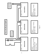
add units in the middle and set them up and connected them in the same way as the middle unit
in the diagram.
The remote control inputs should be connected to the first unit, and the same control options are
available as for a single-unit system. If confirmation feedback is required for a central controller
use the aux relay contacts on the last unit.
The delay times should be set the same for all the SEQs unless you want to skew the turn-on or
turn-off points from one unit to the next.
If the low and high voltage shutdown points are narrowed from their defaults of 90V and 150V
this should be done on the first unit only. The other units should be left set to 90V and 150V.The
two restore options should only be enabled (if required) on the first unit. The self-test shutdown
should be the same for all units.
If an over-ride is required connect it to the first unit.
6.5
Cascaded System
A cascaded system consists of two or more SEQs connected together such that they turn on and
off one after another in an extended sequence. Connecting a cascaded system together is a little
more complicated than the other types of system because there must be feedback from each unit
to the previous unit as well as control from each unit to the next unit. The 12V dc output
(terminal 4) is used as the feedback source and the over-ride input (terminal 3) is used as the
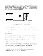
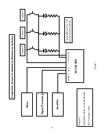
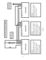
feedback input. Figure 5 shows how to connect and program each unit in a three-unit system.
Note that terminals 5 and 6 are connected together for all units except the last one. If only two
units are to be cascaded together then ignore the middle unit in the diagram. If more than three
units are to be cascaded together then keep the first and last units set up as shown, add units in
the middle and set them up and connected them in the same way as the middle unit in the
diagram.
The remote control inputs should be connected to the first unit, and the same control options are
available as for a single-unit system. If confirmation feedback is required for a central controller
use the aux relay contacts on the last unit.
The delay times should be set as required for the application.
If the low and high voltage shutdown points are narrowed from their defaults of 90V and 150V
this should be done on the first unit only. The other units should be left set to 90V and 150V.The
two restore options should only be enabled (if required) on the first unit. The self-test shutdown
should be the same for all units.
If an over-ride is required connect it to the last unit and program that unit to accept the type of
over-ride you need.

