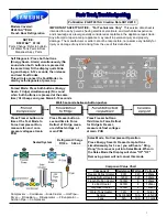
FREEZER DEFROSTING SYSTEMS IN THE FROST FREE MODELS.
This system is activated in a cycle determined by the timer operation in charge of its electric operation sequence. On the
other hand, the thermofuse thermostat has the resistance operation control in order to avoid overheating and damages
caused by overloads (see figure B10-A and B10-B).
The elements in this system are the following:
Defrosting Resistance (figure B10-A)
Is the heater component in charge of melting the frost accumulated in the fins evaporator and operated acoording to the
thermofuse thermostat contacts and the timer contacts. It is located in the evaporator inferior zone and is fixed to it
through aluminum belts or presses according to the design.
Thermofuse thermostat (figure B10-A)
This component is located in the fins evaporator left upper zone to guarantee the adequate performance of the defrosting
resistance fixed with plastic belts and its own shield. This device is in charge of controlling the defrosting resistance
connection by closing the circuit initially, only if the evaporator temperature is under the water freezing point (-9±2°C),
and disconnecting it when the evaporator temperature is higher than the water freezing point (+8±2°C) to guarantee the
coil and fins total defrosting. Besides, in case of thermostat and / or timer failure, it has a fuse to open the circuit and
avoid an overheating due to the resistance ongoing operation in a temperature higher limit value (+62±4°C).
Timer (figure B10-B)
This is an electro – mechanic device formed by a synchronous motor measuring the connections instants of the
defrosting resistance, thanks to the effect of a cam that rotates with the synchronous motor and moves contactors
energizing the resistance. Its electric connection makes the motor work only if the compressor is operating, although it
can have 8 to 6 hour cycles ending when the motor works continuously, defrosting is made once or twice a day. The
defrosting period is 21 or 25 minutes but decreases with the thermofuse thermostat intervention. This component is
located in the left upper zone of the compressor cavity in the cabinet external part.
PAGE . B11
Figure B10-B Defrosting Timer
Figure B10-A Thermofuse Thermostat and Defrosting
Resistance
RESISTANCE
THERMOFUSE THERMOSTAT
TIMER
Содержание 20060328
Страница 1: ...Service Manual Refrigerators 20060328...
Страница 4: ...SERIAL LABEL INFORMATION PAGE A2 SERIAL NUMBER LABEL LOCATION...
Страница 44: ...CATOLOGO DE PARTES SPARE PARTS CATALOG...
Страница 55: ...k ENSAMBLE CONDENSADOR ASSEMBLY CONDENSER SNR10TFPA SNR12TFOA SNR12TFPA SNR13TFOA SNR13TFPA SNR14TFPA...