


Service Manual
SummaSign
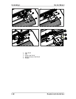
REPLACING THE SENSORS
Cutters are equipped with two sensors. One is located at the front and the other at the rear of the
machine.
84.
Note:
85.
When one sensor is malfunctioning it is advisable to replace both sensors.
Experience has shown that soon after replacing the broken sensor, the other sensor
tends to start malfunctioning as well. Therefore, to prevent having to perform the
same repair twice within a short span of time, it is advisable to replace both
sensors.
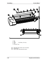
To replace the sensors, proceed as follows:
131.Remove the right-hand cover (see Chapter 2.2, Removing the right hand cover).
132.Turn the unit upside down.
133.Remove the bottom plate (
see
Chapter 2.3, Removing the bottom plate).
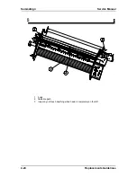
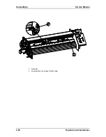
134.Remove the screws holding the two sensors in place. Pay close attention to the positioning of the
distance sleeves. They should be returned to their original location when re-installed.
135.Disconnect the other end of the sensor wire from the PCB.
136.Remove the sensors.
To re-install, proceed in the reverse order of removal. Make sure to firmly tighten all screws.
86.
Caution:
87.
Make sure the sensor wire does not touch the drum. The rotating drum may
damage the wire and cause malfunctioning.
137.
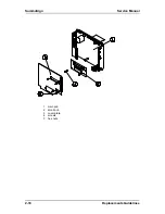
REPLACING THE FAN MOTOR
138.
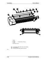
To replace the fan motor, proceed as follows:
139.Remove the right-hand cover (see Chapter 2.2, Removing the right hand cover).
140.Turn the unit upside down.
141.Remove the bottom plate (see Chapter 2.3, Removing the bottom plate)
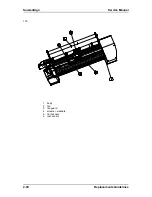
142.Remove the four screws holding the fan motor in place.
143.Disconnect the other end of the fan motor wire from the PCB.
144.Remove the fan motor.
To re-install, proceed in the reverse order of removal. Make sure to firmly tighten all screws.
88.
Caution:
89.
Do not overtighten the 4 screws holding the fan in place as this may bend the
fan's mounting flanges and cause malfunction.
90.
Replacement Guidelines
2-31
Содержание SummaSign D1010
Страница 1: ...Service Manual SummaSign Series Summa NV Rochesterlaan 6 8470 Gistel Belgium...
Страница 62: ...SummaSign Service Manual 2 18 Replacements Guidelines 1 main pcb 2 small pcb 3 cover plate 4 screws 5 hex nuts...
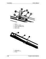
Страница 72: ...SummaSign Service Manual 2 28 Replacements Guidelines 1 Strip Pur 2 unscrew the one closest to the head...
Страница 80: ...SummaSign Service Manual 106 107 2 36 Replacements Guidelines Blank page...
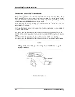
Страница 85: ...Service Manual SummaSignT se 3 2 OPERATING VOLTAGE CONVERSION Maintenance and Cleaning 3 5...
Страница 87: ...Service Manual SummaSignT se Maintenance and Cleaning 3 7 blank page...
Страница 92: ...Service Manual SummaSign Calibration 4 5...
Страница 93: ...SummaSign Service Manual HEAD CALIBRATION 4 6 Calibration...
Страница 131: ...Service Manual SummaSign Spare Parts List 7 13...
Страница 134: ...Summasign Service Manual 7 16 Spare Parts List...


