


11.Unscrew the motor(s). 3 screws a piece. There is no need to disconnect them, just lay them
apart.
12. Remove the x-pulley. (1 or 2 setscrews)
13. Remove the plastic endplate. This plate is held with only1 screw situated near the drum (up-
left).
14.Unscrew the guiding rol near the machine. On the other side the rol is fixed with (removable)
loctite so the screw on the left side should come loose the first.
15. Remove the two caps from the screws holding the rear guiding rol. Remove the rol.
16. Remove the star lock from the pinch roller bar. Remove the nylon bush.
17. Measure the distance between the base plate and the top beam. Also check the
perpendiculrity between the top beam and the base plate. Write down and remember the
values, you will have to reassemble the unit in exact the same way.
18. Put something soft between the base and the table and between the base and the top beam.
19. Unscrew the left steel plate. (6 screws) if it does not have to be replaced, then just put a
little bit aside just enough to reach the faulty components.
20. Now the camroller assys or the headcarriage can be removed. The headcarriage sits
between the outer camrollercarriages and has to be removed if there is a defect with the right
camroller.
21. Remove and replace the faulty components.
3.
!! If a Ccamroller assy is replaced, make sure the plastic cam inside the
assy is
4.
positioned the same way as the one the are removed!!
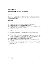
To reassemble:
22.Reseat hte left steel plate.
23.First secure the base plate with three screws, beginning with the one closest to the drive drum.
Screw the first one almost completely in, the check whether the sideplate is perpendicular
to the table then secure it. The hight of the base will be almost correct since the diameter
of the hole in the siede plate for this screw is the smallest. Then secure the side plate to
the base with the other two screws.
24.Secure the top-beam with three screw, beginning with the lowest one. check the hight and
perpendicularity between the base and the top beam before thightining the screw. Adjust if
necessary. Secure the top beam with the other two screws.
25.Proceed in the reverse order of removal starting from 16.
26.
5.
CAUTION
6.
While reinstalling the belt, make sure the right double pulley seats in its
place
7.
Also make sure the long y-belt follows the right path
Check the hight between the nose piece or knife holder and the cutting strip left and right, if they
differ more then .3mm then the base has to be adjusted a little bit.
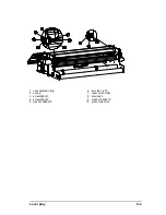
Left Plate Removal
A-
2
Содержание SummaSign D1010
Страница 1: ...Service Manual SummaSign Series Summa NV Rochesterlaan 6 8470 Gistel Belgium...
Страница 62: ...SummaSign Service Manual 2 18 Replacements Guidelines 1 main pcb 2 small pcb 3 cover plate 4 screws 5 hex nuts...
Страница 72: ...SummaSign Service Manual 2 28 Replacements Guidelines 1 Strip Pur 2 unscrew the one closest to the head...
Страница 80: ...SummaSign Service Manual 106 107 2 36 Replacements Guidelines Blank page...
Страница 85: ...Service Manual SummaSignT se 3 2 OPERATING VOLTAGE CONVERSION Maintenance and Cleaning 3 5...
Страница 87: ...Service Manual SummaSignT se Maintenance and Cleaning 3 7 blank page...
Страница 92: ...Service Manual SummaSign Calibration 4 5...
Страница 93: ...SummaSign Service Manual HEAD CALIBRATION 4 6 Calibration...
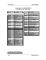
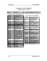
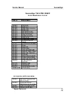
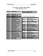
Страница 131: ...Service Manual SummaSign Spare Parts List 7 13...
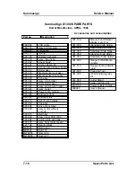
Страница 134: ...Summasign Service Manual 7 16 Spare Parts List...


