
62
8. Daily Inspection and Maintenance
■
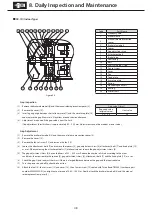
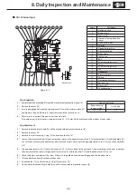
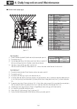
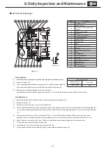
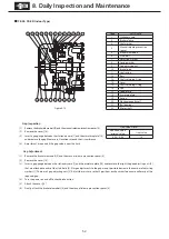
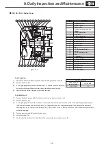
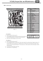
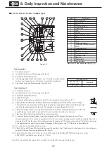
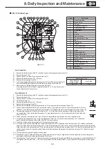
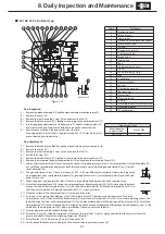
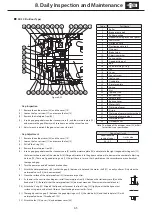
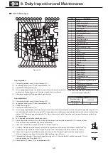
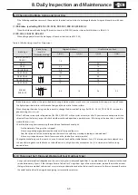
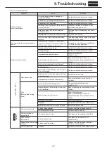
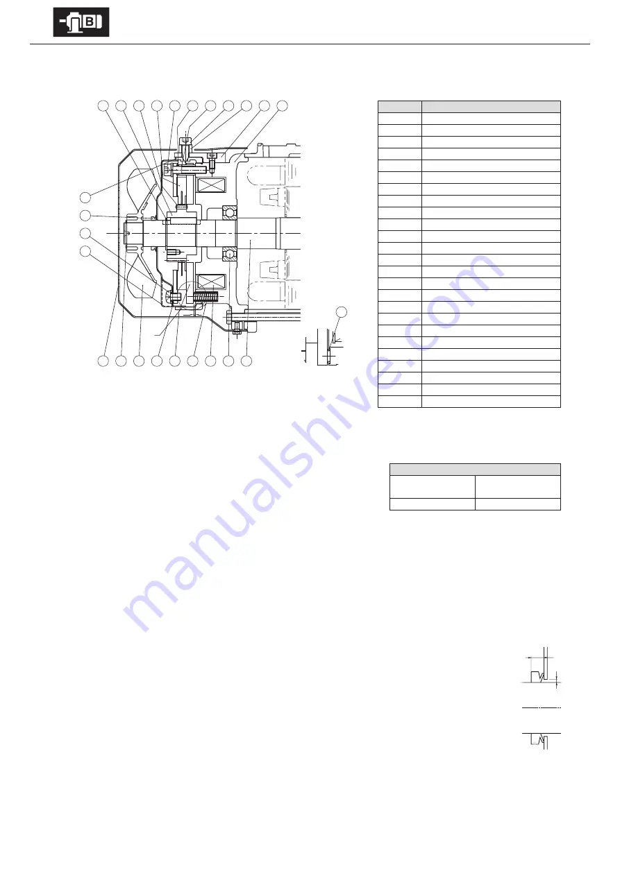
FB-3E, FB-4E (Outdoor Type)
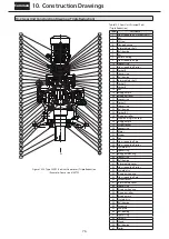
Code
Part Name
1
Stationary core
2
Brake release
3
Manual release prevention spacer
4
Brake release bolt
5
Spacer
6
Gap adjusting shims
7
Attachment bolt
8
Brake lining
9
Leaf spring
10
Boss
11
Shaft-retaining C-ring
12
Cover
13
Shaft-retaining C-ring
14
Fan
15
Fixed plate
16
Armature plate
17
Spring
18
Electromagnetic coil
19
Ball bearings
20
Motor shaft
21
Waterproof seal
22
V-ring
23
Waterproof cover attachment bolts
24
Waterproof cover
25
Shock absorber
1
2
3
4
5
6
7
8
9
10
11
G
12 13 14 15 16 17 18 19 20
21
22
23
24
X
Details for X
25
-
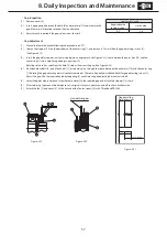
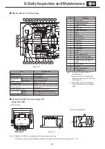
Gap Inspection
(1) Remove the brake release bolt [4] and the manual release prevention
spacer [5].
(2) Remove the cover [12].
(3) Remove the shaft-retaining C-ring [13] and the fan [14].
(4) Remove the brake release [2] (2 locations) and remove the waterproof seal [21].
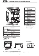
(5) Insert a gap gauge between the stationary core [1] and the armature plate [16]
and measure the gap. Measure in 3 locations around the circumference.
(6) Adjustment is required if the gap value is near the limit.
(Gap adjustment shim thickness is approximately 0.45 – 0.55 mm. Adjustment
cannot be made at a lower value.)
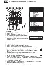
-
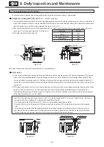
Gap Adjustment
(1) Remove the brake release bolt [4] and the manual release prevention spacer [5].
(2) Remove the cover [12].
(3) Remove the shaft-retaining C-ring [13] and the fan [14].
(4) Pull off the V-ring [22].
(5) Remove the brake release [2] (2 locations) and remove the waterproof seal [21].
(6) Remove the waterproof cover attachment bolts [23], and remove the waterproof cover [24].
(7) Loosen the attachment bolts [7] and remove the spacers [5], gap adjustment shims [6], attachment bolts [7] and fixed plate [15]
as a set. When removing the attachment bolts [7] make certain not to omit the gap adjustment shims [6] or the shock absorber
[25].
(8) The gap adjustment shims [6] have a thickness of 0.45 – 0.55 mm. Reduce the number of shims according to the
wear conditions, then reassemble the spacers [5], gap adjustment shims [6], attachment bolts [7] and fixed plate
[15] as a set.
(9) Check the gap G, and readjust the shims if there is a large difference between it and the required value.
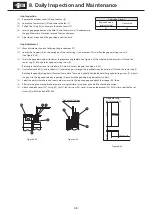
(10) Attach the waterproof cover [24] using the waterproof cover attachment bolts [23]. At this time align the cutout
area on the side of the waterproof cover [24] with the brake release bolt [4]. Attach the waterproof cover [24] so
that the gap (A) between its hole and the motor shaft [20] is nearly uniform.
(11) Clean the surface of the waterproof seal [21] to remove impurities.
(12) As shown in the construction diagram, install the waterproof seal [21] between the stationary core [1] and the
waterproof cover [24]. Then attach the brake release [2]. Align the hole in the waterproof seal [21] for the brake
release bolt with the position of the release bolt [4]. Attach the waterproof seal [21] so that its protrusion fits
snuggly around the entire circumference of the groove for the stationary core [1]. (Be careful that the waterproof
seal [21] does not meander. Otherwise water could leak in.)
(13) Turn the power on and off to check brake action.
(14) Attach the V-ring [22]. Wipe off the lip and surface near the lip of the V-ring [22], lightly coat the the lip contact surface with
grease, and attach. Observe the attaching dimension (B
=
6mm).
(15) Attach the fan [14], shaft-retaining C-ring [13] and cover [12].
(16) Finally, attach the brake release bolt [4] and the manual release prevention spacer [3].
Gap value G (mm)
Required value
(original value)
Limit value
0.25 – 0.35
0.85
B
A
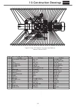
Figure 8-26


