30
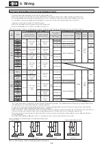
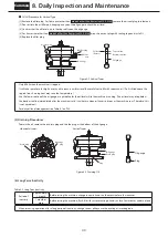
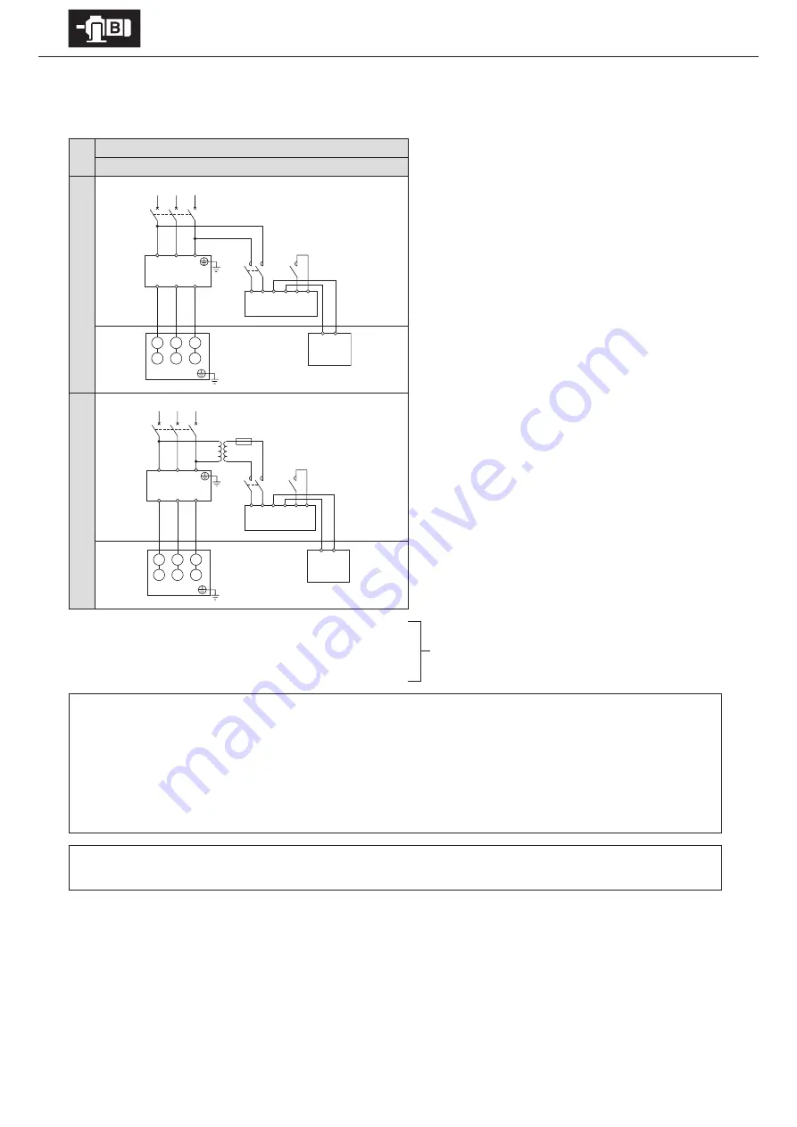
6. Wiring
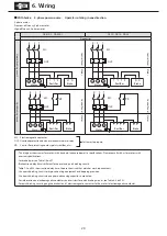
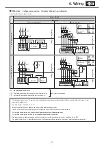
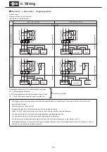
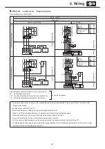
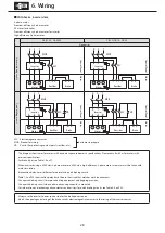
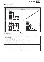
■
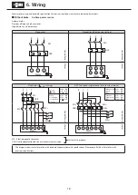
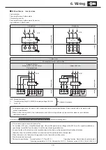
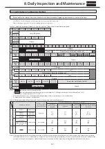
With brake Inverter drive
Premium-efficiency, 3-phase motor
Premium-efficiency, 3-phase motor for inverter
ESB-250, ESB-250-2
8 lead wires
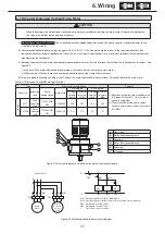
Q
uick br
ak
ing cir
cuit 200V class
Con
tr
ol P
anel
M
ot
or
Q
uick br
ak
ing cir
cuit 400V class
Con
tr
ol P
anel
M
ot
or
MC: Electromagnetic contactor
MCB: Breaker for wiring
Tr: Transformer capacity 250–600VA, secondary voltage 200–220V
F:
Fuse 3–5A
Customer to prepare.
-This diagram shows cases for motors with standard Japanese domestic specifications. Please consult with us for motors with
overseas specifications.
-For brake types, see Table 1-6 on P7.
-Use with a quick braking circuit. For information on electromagnetic contactors for quick braking circuits, see Table 6-4 on P32.
-Rectifiers are external to the main unit. Rectifiers are made for indoor use. Install in an area where they will not come into contact
with water, etc.
-The brake unit is for 200V class. For 400V class power sources, prepare a 400V/200V transformer.
-Always use the inverter’s power source side for the brake power source.
-Match the opening and closing of the brake circuit’s electromagnetic contactor to the timing of the inverter control.
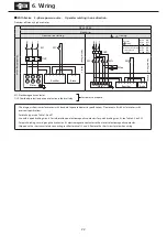
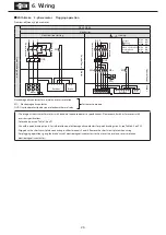
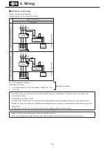
R S T
Inverter
R
S
T
U
V
W
U1
V1 W1
V2 W2 U2
1 2 3 4 5 6
4 3
Rectifier
Brake
MCB
MC
Tr
F
400V
200V
Motor
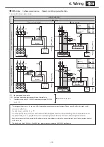
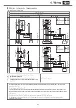
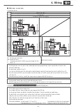
R S
T
Inverter
R
S
T
U
V
W
U1
V1 W1
V2 W2 U2
1 2 3 4 5 6
4 3
Rectifier
Brake
MCB
MC
Motor


