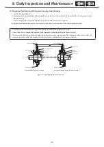
31
30
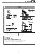
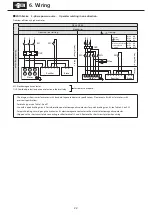
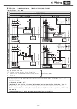
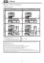
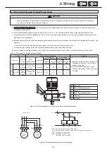
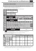
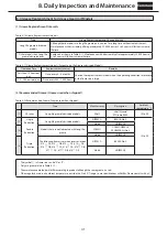
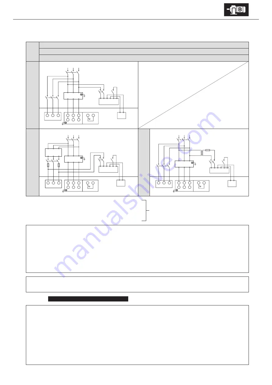
6. Wiring
■
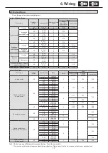
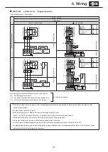
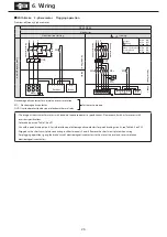
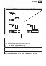
With brake Inverter drive
AF motor for inverter
ESB-250, ESB-250-2
13 lead wires
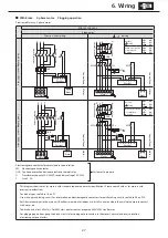
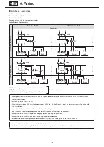
AF motor for inverter with axial fan
Q
uick br
ak
ing cir
cuit
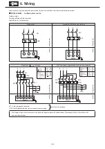
Indoor 200V class
O
ut
door 200V class
Con
tr
ol P
anel
M
ot
or
Q
uick br
ak
ing cir
cuit
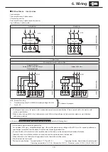
Indoor 400V class
Con
tr
ol P
anel
Q
uick br
ak
ing cir
cuit
O
ut
door 400V class
Con
tr
ol P
anel
M
ot
or
M
ot
or
MC: Electromagnetic contactor
MCB: Breaker for wiring
Tr: Transformer capacity 250–600VA, secondary voltage 200–220V
F:
Fuse 3–5A
Customer to prepare.
-This diagram shows cases for motors with standard Japanese domestic specifications. Please consult with us for motors with
overseas specifications.
-For brake types, see Table 1-6 on P7.
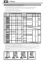
-Use with a quick braking circuit. For information on electromagnetic contactors for quick braking circuits, see Table 6-4 on P32.
-Rectifiers are external to the main unit. Rectifiers are made for indoor use. Install in an area where they will not come into contact
with water, etc.
-The brake unit is for 200V class. For 400V class power sources, prepare a 400V/200V transformer.
-Always use the inverter’s power source side for the brake power source.
-Match the opening and closing of the brake circuit’s electromagnetic contactor to the timing of the inverter control.
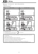
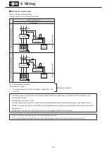
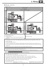
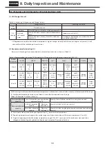
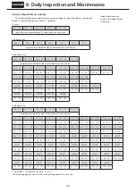
In the case of
With axial fan (totally enclosed, ventilated types)
, note the following items.
-Also connect a power source to the axial fan.
-For an indoor 400V class, the axial fan power source voltage will be 200V class.
-For special specifications, specifications may differ from the above. Check the manufacturing specifications.
-Connect the fan so that it rotates in the same direction as that shown on the nameplate for direction of rotation.
(Normally, the air from the fan will blow in a direction from the anti-load side to the load side.)
-When the motor is shut down for a long period, also shut down the axial fan motor.
-Wire the mounted thermostat.
-Thermostat specification: Terminal symbols: T1, T2 and P1, P2
Operating function: Normal close (b contact point)
Operating temperature: 135
℃
(for thermal class 155 (F))
Maximum current: DC 24V, 18A; AC 230V, 13A
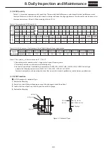
U1
V1
W1
V2
W2
T1
T2
U2
R
U
V
W
S
T
MCB1
MCB2
Motor
Thermostat
Axial fan
Inverter
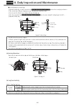
R
S
T
U
V
W
U
V
W
MCB2
F
F
Axial fan
400V
Tr
200V
U1
V1
W1
V2
W2
U2
R
S
T
MCB1
Motor
Inverter
R
S
U
V
W
T
T1
T2
Thermostat
1 2 3 4 5 6
4
3
Rectifier
Brake
MC
U1
V1
W1
V2
W2
T1
T2
U2
R
U
V
W
S
T
MCB1
MCB2
Motor
Thermostat
Axial fan
Inverter
R
S
T
U
V
W
1 2 3 4 5 6
4
3
Rectifier
MC
1 2 3 4 5 6
4
3
Rectifier
Brake
MC
Tr
F
400V
200V
Brake


