


24
6. Wiring
■
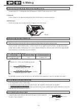
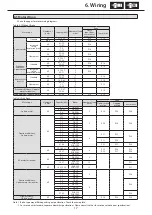
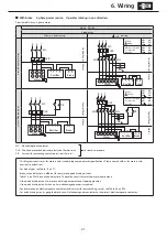
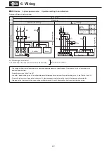
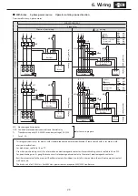
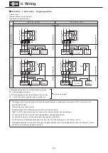
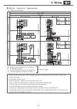
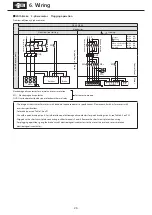
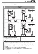
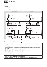
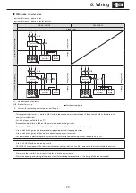
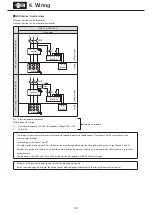
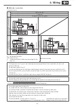
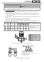
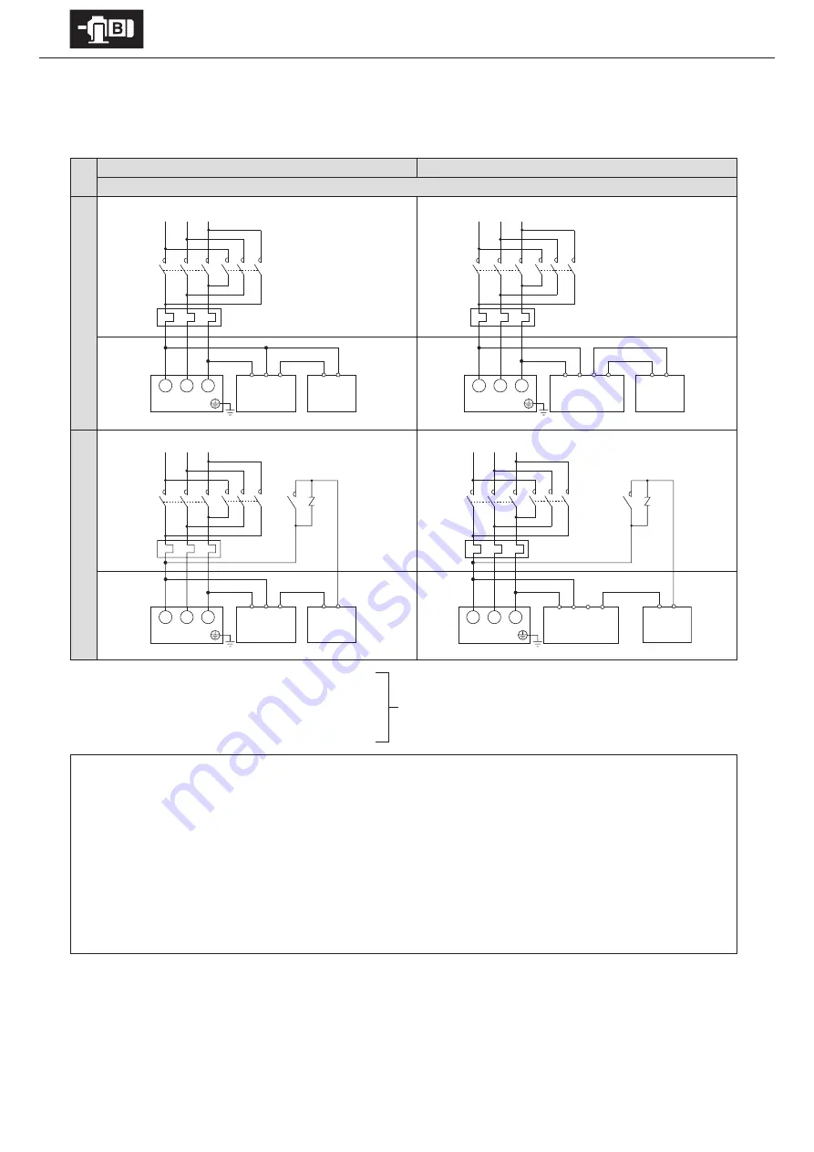
With Brake. 3-phase motor. Plugging operation
3-phase motor
Premium-efficiency, 3-phase motor
High-efficiency, 3-phase motor
FB-01A1 – FB-05A1
FB-1D, FB-1E – FB-5E
5 lead wires
Nor
mal br
ak
ing cir
cuit
Con
tr
ol P
anel
Con
tr
ol P
anel
M
ot
or
M
ot
or
Q
uick br
ak
ing cir
cuit
Con
tr
ol P
anel
Con
tr
ol P
anel
M
ot
or
M
ot
or
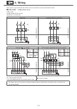
Electromagnetic contactor for normal and reverse rotation
MC: Electromagnetic contactor
OLR: Overload protection device or electronic thermal relay
VR: Varistor (for protecting contact points, rectifier, etc.)
Customer to prepare.
-This diagram shows cases for motors with standard Japanese domestic specifications. Please consult with us for motors with
overseas specifications.
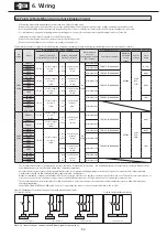
-For brake types, see Table 1-6 on P7.
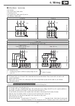
-Brake action delay time is different for normal and quick braking circuits.
Table 7-2 on P35 shows action delay time. Choose the circuit that matches work requirements.
-Use a quick braking circuit to improve hoisting equipment and stopping precision.
-Use a quick braking circuit when a phase-advancing capacitor is mounted.
-For information on electromagnetic contactors and varistors for quick braking circuits, see Table 6-4 on P32.
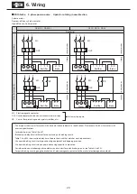
-For plugging operations using a quick- braking circuit, gang the brake circuit’s electromagnetic contactors to the motor’s normal
and reverse rotation electromagnetic contactors.
U
V
W
1 2 4
M N
Rectifier
Brake
U
V
W
1 2 4
M N
Rectifier
Brake
U
V
W
M N
Brake
U
V
W
1 2 3 4
M N
Rectifier
Brake
Motor
VR
Motor
MC
MC
1 2 3 4
Rectifier
R
S T
OLR
R
S T
OLR
Motor
R
S T
OLR
VR
Motor
R
S T
OLR
Normal rotation
Normal rotation
Rev
erse rotation
Rev
erse rotation
Normal rotation
Normal rotation
Rev
erse rotation
Rev
erse rotation


