33
COMPONENT DESCRIPTION
3.8.3
BLOWDOWN SOLENOID VALVE
The blowdown solenoid valve opens to vent airflow from the sump tank to the atmosphere. The opening of
the valve is controlled by the adjustable set point of the microprocessor
. Air from the blowdown solenoid
valve is vented back to the inlet air filter to reduce noise during blowdown.
The blowdown solenoid valve is
located on the upper side of the sump tank.
3.8.4 LINE PRESSURE TRANSDUCER (P2)
The line pressure transducer (P2) controls the load/unload of the compressor by opening or closing the
blowdown solenoid valve based on the line pressure setting in the microprocessor. This set point for
blowdown control is typically 10 psi over the desired setting of line pressure. The transducer also allows for
line pressure indication during the operation of the compressor via the microprocessor. These settings are
initially determined by the Factory, but may be adjusted accordingly within the limitations of the compressor
.
3.9
MONITORING SYSTEM
The monitoring system utilizes the microprocessor to compile data through the use of sump pressure
transducer (P1), line pressure transducer (P2) and compressor unit discharge temperature sensor. The
components control system load/unload, safety shut-downs, and allow for visual display of the values
through the microprocessor.
Содержание UD Series
Страница 6: ...vi About This Manual ...
Страница 12: ...4 Introduction ...
Страница 24: ...16 Specifications 2 2 DIMENSIONS OPEN AIR COOLED 230V Figure 2 1 GA 30 40 50UD AC VFD 230V R00 ...
Страница 25: ...17 Specifications 2 3 DIMENSIONS OPEN AIR COOLED 460V Figure 2 2 GA 30 40 50UD AC MPC VFD OPEN 460V R00 ...
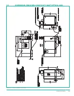
Страница 26: ...18 Specifications 2 4 DIMENSIONS ENCLOSED AIR COOLED 460V Figure 2 3 GA 40 50 60UDAC ENC S1 R00 ...
Страница 27: ...19 Specifications 2 5 DIMENSIONS ENCLOSED HEAVY DUTY INLET OPTION 460V Figure 2 4 GA 40 50 60UDAC VFD ENC R00 ...
Страница 28: ...20 Specifications 2 6 DIMENSIONS ENCLOSED AIR COOLED HD INLET NO BUSSEL Figure 2 5 GA 60UDAC ENC VFD NB R00 ...
Страница 29: ...21 Specifications 2 7 PIPING AND INSTRUMENTATION AIR COOLED Figure 2 6 P I 15 40D AC MPC VFD R02 ...
Страница 42: ...34 Component Description ...
Страница 52: ...44 Operation ...
Страница 66: ...58 Troubleshooting ...
Страница 74: ...66 Parts Catalog 8 5 COMPRESSOR FRAME AND DRIVE ASSEMBLY Figure 8 1 AS801 25UD 50UD VFD R00 ...
Страница 76: ...68 Parts Catalog 8 6 CONTROL ASSEMBLY OPEN Figure 8 2 1072190415 609 R00 ...
Страница 78: ...70 Parts Catalog 8 7 STARTER ASSEMBLY ENCLOSED Figure 8 3 AS802 405060 PANEL R03 ...
Страница 80: ...72 Parts Catalog 8 8 AIR INLET ASSEMBLY 15 30HP 13 12 11 13 12 4 5 2 3 14 1 Figure 8 4 AS805 030D7H TE R00 ...
Страница 94: ...86 Parts Catalog 8 15 COOLING ASSEMBLY AIR COOLED Figure 8 11 AS804 50UDAC INLINE R00 ...
Страница 100: ...NOTES ...
Страница 101: ...NOTES ...

