background image

22

SPECIFICATIONS

2.8 

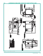
WIRING DIAGRAM, AIR-COOLED, 208/230/460V 

DWG NO.

DATE:

MATL:

DRAWN BY:

00

DO NOT SCALE DRAWING

TOLERANCES

UNLESS OTHERWISE NOTED
DIMENSIONS ARE IN INCHES

ANGLES....... ±1/2 °
MACHINED......±1/64"
STRUCTURAL....±1/16"
DECIMAL:
    0" TO 12"....030"
   12" TO 36"....060"
   36" TO........125"

A

SULLIVAN

PALATEK

1201 W. US HIGHWAY 20   Michigan City, Indiana  46360

GET

N/A

SHEET:

1 OF 1

REV

1

23

1

22

1

21

1

20

1

19

1

18

1

17

1

16

1

15

1

14

1

13

1

12

1

11

1

10

1

09

1

08

1

07

1

06

1

05

1

04

1

03

1

02

1

01

1

24

00

01

02

03

DESCRIPTION BEFORE CHANGE

DATE

BY:

NO.

SIZE

SCALE:

CONFIDENTIAL  INFORMATION. IT MUST BE USED STRICTLY FOR THE LIMITED PURPOSE
SUBMITTED AND IS SUBJECT TO RETURN UPON DEMAND. ANY DISCLOSURE, REPRODUCTION
OR OTHER USE IS EXPRESSLY  PROHIBITED EXCEPT AS OTHERWISE AGREED UPON IN WRITING.

THIS DOCUMENT IS THE PROPERTY OF PALATEK INC. AND CONTAINS PROPRIETARY AND

UD-SERIES, VFD AND T1 MPC 

8/19/2019

CB111

2A

V

I

SW1

-

+2

V

I

THERMAL

OVERLOAD

(OPTIONAL)

VFD 1

YASKAWA A1000

MAIN MOTOR DRIVE

RUN SIGNAL

FROM T1 XO3

VFD 2
YASKAWA V1000

FAN MOTOR DRIVE

T111
50VA XFMR

120/24 VAC

1

4
3

2
1

1

2

3

4

5

6

2
1

C8

C7

C5

C4

C3

C2

C1

C+

C6

2

1

2
1

2

1

BLK

WHT

1

2

3

4

5

6

-

+

-

+

WD-00131

8/19/2019

RELEASED, ECO 604

GET

N/A

WHT

BLK

HEATER LOADS

FIGURE 2-7. 

WD-00131 R00

Содержание UD Series

Страница 1: ...USER MANUAL INDUSTRIAL ELECTRIC UPDRAFT COMPRESSOR 25 50hp Document 18730 101 00 Issued November 22 2019 UD SERIES T1 MICROPROCESSOR CONTROLLER VARIABLE FREQUENCY DRIVE ...

Страница 2: ...EPING Record the model and serial number of the compressor for future reference when contacting the Factory for service or parts Model Number Serial Number DISCLAIMER Although this manual is checked for conformity with the machines described we cannot guarantee that all errors will be excluded Necessary corrections will be made in future editions of this manual This manual is subject to change wit...

Страница 3: ... and maintenance items the consequences of service performed by someone other than a party authorized to perform warranty service if such service in the judgment of Sullivan Palatek has adversely affected the performance of the compressor the consequences of negligence misuse accident installation or storage The consequences of compressor lubrication neglect as manifested by varnishing pitting ero...

Страница 4: ... remainder of the warranty period applicable to the replaced part Registration and Obtaining Warranty Service The Warranty Registration Form supplied with the compressor must be completed and returned within 10 days of delivery and start up to register the compressor under the Platinum program Eligibility for the Platinum Warranty will expire 180 days after shipment of the product from the factory...

Страница 5: ...g information related to the specific air compressor such as application data and drawings SECTION 3 COMPONENT DESCRIPTION This section contains information about how the different systems and components function within an air compressor SECTION 4 INSTALLATION This section contains information and guidelines to follow when choosing a site for and installing the air compressor SECTION 5 OPERATION T...

Страница 6: ...vi About This Manual ...

Страница 7: ...ir Cooled 21 2 8 Wiring Diagram Air Cooled 208 230 460V 22 2 9 Wiring Diagram Water Cooled 208 230 460V 23 2 10 Wiring Diagram Cold Weather Kit 24 3 COMPONENT DESCRIPTION 25 3 1 Air Compressor Package 26 3 2 Compression Cycle 26 3 3 Drive System 26 3 4 VFD Electrical Control Panel 26 3 5 Protective Devices 26 3 6 Air Oil Discharge System 27 3 7 Cooling and Lubricating System 28 3 8 Air Inlet and C...

Страница 8: ...ull Discharge Pressure 56 7 4 Machine Short Cycles Between Load Unload 56 7 5 Pressure Relief Valve Opens Repeatedly 56 7 6 Excessive Lubricant Consumption 56 7 7 Machine Shuts Down With Air Demand Present 57 8 PARTS CATALOG 59 8 1 Ordering Parts 60 8 2 Parts Drawings 60 8 3 Recommended Spare Parts List 61 8 4 Compressor Lubricants 62 8 5 Compressor Frame and Drive Assembly 66 8 6 Control Assembly...

Страница 9: ...1 1 INTRODUCTION TOPICS IN THIS SECTION General Compressor Safety Precautions 2 Safety Decals 2 Screw Compressor Air End Exchange Program 3 ...

Страница 10: ...ersonal protective equipment per OSHA Standard 29 CFR 1910 242 b Keep all parts of the body away from all potential points of air discharge including pressure relief valve ports hoses or tools Avoid bodily contact with hot oil hot surfaces sharp edges and corners Serious injury or death may result from horseplay with air hoses and compressed air Do not do it do not allow it Do not operate the comp...

Страница 11: ...pon the owner lessor or other responsible administrator to be sure the operator is properly trained made aware of and understands the meaning of all warning decals 1 3 SCREW COMPRESSOR AIR END EXCHANGE PROGRAM After the warranty period has expired a factory remanufactured air end can be purchased on an exchange basis All bearings and seals in the factory remanufactured air end are replaced All oth...

Страница 12: ...4 Introduction ...

Страница 13: ...nsions Open Air Cooled 230V 16 Dimensions Open Air Cooled 460V 17 Dimensions Enclosed Air Cooled 460V 18 Dimensions Enclosed Heavy Duty Inlet Option 460V 19 Dimensions Enclosed Air Cooled HD Inlet No Bussel 20 Piping and Instrumentation Air Cooled 21 Wiring Diagram Air Cooled 208 230 460V 22 Wiring Diagram Water Cooled 208 230 460V 23 Wiring Diagram Cold Weather Kit 24 ...

Страница 14: ...llons liters 4 5 17 3 5 13 COOLING DATA WATER COOLED UD 25 Water Flow with 60 F Water gpm L min 3 11 4 Water Flow with 70 F Water gpm L min 3 7 14 0 Water Flow with 80 F Water gpm L min 5 18 9 Maximum Water Temperature F C 85 29 Water Connection In Out NPT 3 4 3 4 NOTE Supplied water pressure should be between 25 75 psig 1 7 5 2 bar SOUND DATA UD 25 Air Cooled Open dba 1m 85 Air Cooled Enclosed db...

Страница 15: ...ODP Motor Insulation Class NEMA F Motor Service Factor NEMA 1 25 Motor Maximum Starts Hour 4 DIMENSIONS OPEN UD 25 Length inches mm 66 1676 Width inches mm 34 10 866 Height inches mm 47 12 1197 Weight lbs kg DIMENSIONS ENCLOSED UD 25 Length inches mm 80 2032 Width inches mm 35 889 Height inches mm 49 1245 Weight lbs kg ...

Страница 16: ... 17 3 5 13 4 5 17 3 5 13 COOLING DATA WATER COOLED UD4 25 UD4 H25 UD4 HH25 Water Flow with 60 F Water gpm L min 3 11 4 3 11 4 3 11 4 Water Flow with 70 F Water gpm L min 3 7 14 0 3 7 14 0 3 7 14 0 Water Flow with 80 F Water gpm L min 5 18 9 5 18 9 5 18 9 Maximum Water Temperature F C 85 29 85 29 85 29 Water Connection In Out NPT 3 4 3 4 3 4 3 4 3 4 3 4 NOTE Supplied water pressure should be betwee...

Страница 17: ... Motor Maximum Starts Hour 4 4 4 DIMENSIONS OPEN UD4 25 UD4 H25 UD4 HH25 Length inches mm 66 1676 66 1676 66 1676 Width inches mm 34 10 866 34 10 866 34 10 866 Height inches mm 47 12 1197 47 12 1197 47 12 1197 Weight lbs kg TBD TBD TBD DIMENSIONS ENCLOSED UD4 25 UD4 H25 UD4 HH25 Length inches mm 80 2032 66 1676 66 1676 Width inches mm 35 889 34 10 866 34 10 866 Height inches mm 49 1245 47 12 1197 ...

Страница 18: ... 4 5 17 3 5 13 4 5 17 3 5 13 COOLING DATA WATER COOLED UD 30 UD H30 UD HH30 Water Flow with 60 F Water gpm L min 3 11 4 3 11 4 3 11 4 Water Flow with 70 F Water gpm L min 3 7 14 0 3 7 14 0 3 7 14 0 Water Flow with 80 F Water gpm L min 5 18 9 5 18 9 5 18 9 Maximum Water Temperature F C 85 29 85 29 85 29 Water Connection In Out NPT 3 4 3 4 3 4 3 4 3 4 3 4 NOTE Supplied water pressure should be betwe...

Страница 19: ...25 Motor Maximum Starts Hour 4 4 4 DIMENSIONS OPEN UD 30 UD H30 UD HH30 Length inches mm 66 1676 66 1676 66 1676 Width inches mm 34 10 866 34 10 866 34 10 866 Height inches mm 47 12 1197 47 12 1197 47 12 1197 Weight lbs kg TBD TBD TBD DIMENSIONS ENCLOSED UD 30 UD H30 UD HH30 Length inches mm 80 2032 66 1676 66 1676 Width inches mm 35 889 34 10 866 34 10 866 Height inches mm 49 1245 47 12 1197 47 1...

Страница 20: ...13 4 5 17 3 5 13 COOLING DATA WATER COOLED UD 40 UD H40 UD HH40 Water Flow with 60 F Water gpm L min 4 5 17 0 4 5 17 0 4 5 17 0 Water Flow with 70 F Water gpm L min 5 8 21 0 5 8 21 0 5 8 21 0 Water Flow with 80 F Water gpm L min 7 6 28 8 7 6 28 8 7 6 28 8 Maximum Water Temperature F C 85 29 85 29 85 29 Water Connection In Out NPT 3 4 3 4 3 4 3 4 3 4 3 4 NOTE Supplied water pressure should be betwe...

Страница 21: ...m Starts Hour 4 4 4 DIMENSIONS OPEN UD 40 UD H40 UD HH40 Length inches mm 66 1676 66 1676 66 1676 Width inches mm 34 10 866 34 10 866 34 10 866 Height inches mm 47 12 1197 47 12 1197 47 12 1197 Weight lbs kg 1375 624 1375 624 1375 624 DIMENSIONS ENCLOSED UD 40 UD H40 UD HH40 Length inches mm 80 2032 66 1676 66 1676 Width inches mm 35 889 34 10 866 34 10 866 Height inches mm 49 1245 47 12 1197 47 1...

Страница 22: ...17 3 5 13 4 5 17 3 5 13 COOLING DATA WATER COOLED UD 50 UD H50 UD HH50 Water Flow with 60 F Water gpm L min 5 9 22 3 5 9 22 3 5 9 22 3 Water Flow with 70 F Water gpm L min 7 3 27 6 7 3 27 6 7 3 27 6 Water Flow with 80 F Water gpm L min 9 8 37 1 9 8 37 1 9 8 37 1 Maximum Water Temperature F C 85 29 85 29 85 29 Water Connection In Out NPT 3 4 3 4 3 4 3 4 3 4 3 4 NOTE Supplied water pressure should b...

Страница 23: ...n Motor FLA 575V amps 2 86 2 86 2 86 Fan Motor FLA 575V amps 3 15 3 15 3 15 Fan Motor FLA 575V amps 3 29 3 29 3 29 Fan Motor Enclosure NEMA TEFC TEFC TEFC DIMENSIONS OPEN UD 50 UD H50 UD HH50 Length inches mm 66 1676 66 1676 66 1676 Width inches mm 34 10 866 34 10 866 34 10 866 Height inches mm 47 12 1197 47 12 1197 47 12 1197 Weight lbs kg 1340 608 1340 608 1340 608 DIMENSIONS ENCLOSED UD 50 UD H...

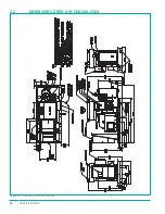
Страница 24: ...16 Specifications 2 2 DIMENSIONS OPEN AIR COOLED 230V Figure 2 1 GA 30 40 50UD AC VFD 230V R00 ...

Страница 25: ...17 Specifications 2 3 DIMENSIONS OPEN AIR COOLED 460V Figure 2 2 GA 30 40 50UD AC MPC VFD OPEN 460V R00 ...

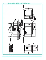
Страница 26: ...18 Specifications 2 4 DIMENSIONS ENCLOSED AIR COOLED 460V Figure 2 3 GA 40 50 60UDAC ENC S1 R00 ...

Страница 27: ...19 Specifications 2 5 DIMENSIONS ENCLOSED HEAVY DUTY INLET OPTION 460V Figure 2 4 GA 40 50 60UDAC VFD ENC R00 ...

Страница 28: ...20 Specifications 2 6 DIMENSIONS ENCLOSED AIR COOLED HD INLET NO BUSSEL Figure 2 5 GA 60UDAC ENC VFD NB R00 ...

Страница 29: ...21 Specifications 2 7 PIPING AND INSTRUMENTATION AIR COOLED Figure 2 6 P I 15 40D AC MPC VFD R02 ...

Страница 30: ...E DATE BY NO SIZE SCALE CONFIDENTIAL INFORMATION IT MUST BE USED STRICTLY FOR THE LIMITED PURPOSE SUBMITTED AND IS SUBJECT TO RETURN UPON DEMAND ANY DISCLOSURE REPRODUCTION OR OTHER USE IS EXPRESSLY PROHIBITED EXCEPT AS OTHERWISE AGREED UPON IN WRITING THIS DOCUMENT IS THE PROPERTY OF PALATEK INC AND CONTAINS PROPRIETARY AND UD SERIES VFD AND T1 MPC 8 19 2019 CB111 2A V I SW1 2 V I THERMAL OVERLOA...

Страница 31: ...SCLOSURE REPRODUCTION OR OTHER USE IS EXPRESSLY PROHIBITED EXCEPT AS OTHERWISE AGREED UPON IN WRITING THIS DOCUMENT IS THE PROPERTY OF PALATEK INC AND CONTAINS PROPRIETARY AND N A DWG NO DATE DRAWN BY 00 TOLERANCES UNLESS OTHERWISE NOTED DIMENSIONS ARE IN INCHES ANGLES 1 2 MACHINED 1 64 STRUCTURAL 1 16 DECIMAL 0 TO 12 030 12 TO 36 060 36 TO 125 A SULLIVAN PALATEK 1201 W US HIGHWAY 20 Michigan City...

Страница 32: ...SCALE 50 60 UD VFD WITH T1 COLD WEATHER KIT WD 00092 1201 Highway 20 West Michigan City Indiana 46360 10 10 2016 N A GET CONFIDENTIAL INFORMATION IT MUST BE USED STRICTLY FOR THE LIMITED PURPOSE SUBMITTED AND IS SUBJECT TO RETURN UPON DEMAND ANY DISCLOSURE REPRODUCTION OR OTHER USE IS EXPRESSLY PROHIBITED EXCEPT AS OTHERWISE AGREED UPON IN WRITING THIS DOCUMENT IS THE PROPERTY OF PALATEK INC AND C...

Страница 33: ...CTION Air Compressor Package 26 Compression Cycle 26 Drive System 26 VFD Electrical Control Panel 26 Protective Devices 26 Air Oil Discharge System 27 Cooling and Lubricating System 28 Air Inlet and Capacity Control System 29 Monitoring System 33 ...

Страница 34: ...powers the compressor unit The electric motor is three phase induction type supplied with a C flange that bolts directly to the motor compressor adapter Standard motor configuration is a NEMA Premium ODP design Optional motor configurations are available upon request 3 3 2 DRIVE COUPLING The drive coupling transfers power from the drive motor to the compressor unit The drive coupling consists of t...

Страница 35: ... the MPV will allow air to pass through to the aftercooler to reduce the temperature of the air from a nominal 180 F to 100 F 82 C to 38 C This change in temperature condenses the water so that it can be removed by a water separator equipped with an electric drain valve After leaving the water separator the compressed air can then begin building pressure in the air system for use 3 6 1 SUMP TANK R...

Страница 36: ...nal clearances 3 7 1 LUBRICANT The compressor lubricant is also referred to as compressor fluid or simply as oil During the compression cycle lubricant is injected directly into the compressor unit The lubricant in a rotary screw compressor serves three primary functions 1 It is a lubricant supplying constant flow between the moving parts along with the bearings and seals 2 It is a coolant removin...

Страница 37: ...MATERIAL IT IS LOANED SUBJECT TO RETURN UPON DEMAND IS NOT TO BE USED DIRECTLY OR INDIRECTLY IN ANYWAY DRAWING NO SIZE FIGURE 3 2 MPC CONTROL SYSTEM LEGEND R00 COMPONENT 1 Line Pressure Transducer P2 2 Sump Pressure Transducer P1 3 Blowdown Solenoid Valve 4 Inlet Control Valve 5 Atmospheric Vent Orifice 6 Vacuum Break Recirculation Valve The air inlet and capacity control system utilizes electrica...

Страница 38: ... and minimum design pressure has been achieved At this time the system is in a blowdown condition during which control air is supplied back to the inlet valve to keep it in a closed position and a controlled amount of air is vented out of the sump tank A predetermined blowdown orifice and an inlet bypass orifice will maintain the unload sump pressure nominal 30 40 psig 2 1 2 8 bar At this time the...

Страница 39: ...During this time no control air will be flowing to any major components As the sump pressure reaches the set point of the minimum pressure valve air flow to customer s process will start The outlet pressure to the customer s process is monitored and will control the blowdown when needed Sump pressure and line pressure are displayed on the control panel to visually monitor the status of the compres...

Страница 40: ...es the stop push button the system will go into an unload condition and blowdown prior to completely shutting down CAUTION The operator should use the E Stop button for emergencies only 3 8 1 INLET AIR FILTER The inlet air filter removes contaminants from the air entering the compressor system through the inlet control valve It is a heavy duty two stage air filter which includes a primary filter e...

Страница 41: ... solenoid valve based on the line pressure setting in the microprocessor This set point for blowdown control is typically 10 psi over the desired setting of line pressure The transducer also allows for line pressure indication during the operation of the compressor via the microprocessor These settings are initially determined by the Factory but may be adjusted accordingly within the limitations o...

Страница 42: ...34 Component Description ...

Страница 43: ... Receiving 36 Moving and Lifting 36 Location and Support 36 Intake Air 36 Ventilation and Cooling 37 Electrical Connections 37 Fluid Level Check 37 Direction of Rotation 37 Compressed Air System 38 Multiple Machine Installation 38 Storage 38 ...

Страница 44: ...re compressor by motor lifting eyes as they are intended only for lifting the motor CAUTION Use extreme care when moving tank mounted compressors because of the high center of gravity Substitution of lifting hardware is not permitted Use only the hardware supplied with the compressor package The use of a sufficiently rated spreader or lifting beam may be required to properly balance the load Be ca...

Страница 45: ...ressor must be appropriate to the area in which it is installed NEMA 1 enclosures are standard but all other ratings are optional upon request NOTE A certified electrician must install the compressor in accordance with the National Electric Code NEC local electrical codes and Occupational Safety and Health Administration OSHA worker safety regulations The compressor must also be grounded properly ...

Страница 46: ...pressor as possible on plane with the discharge of the cooler If a receiver tank is going to be utilized a rule of thumb for sizing would be four gallons per horsepower By adding an air receiver tank in the system the compressor will offer smoother operation through air demands It is also recommended that air enters the receiver tank at a lower port than that of the tank s outlet port Additional e...

Страница 47: ...39 5 Operation TOPICS IN THIS SECTION T1 User Interface 40 Access Codes 42 Prior to Starting 42 Normal Start 42 Normal Stop 42 Restarts 43 ...

Страница 48: ...jump to the next information item To revert back to the normal operational display mode P00 while in menu mode press and hold for longer than two seconds ENTER Confirm selection or value adjustments Press to lock a selected value display and prevent returning to the default display after a short delay When locked the key symbol will flash To unlock press CLEAR It will also return to the default di...

Страница 49: ...Value Item 5 Value Item 6 Value Page 00 Page 01 Page 02 Page 03 Page 04 Page 05 Figure 5 2 NAVIGATION FORWARD MOVEMENT BACKWARD MOVEMENT Press CLEAR at any time in menu mode to step backwards one stage in the navigation process Pressing CLEAR when the page number is flashing will exit menu mode and return the display to normal operational mode P00 Press and hold RESET for two seconds at any time t...

Страница 50: ...s detected for a period of time the display will automatically reset to the normal operational display P00 The timeout period is dependent on the access code used ACCESS CODE TIME OUT PERIOD USER 1 minute SERVICE 1 10 minutes 5 3 PRIOR TO STARTING 5 3 1 PRIOR TO INITIAL START Be familiar with the contents of this manual Be sure that all installation requirements have been met Inspect the compresso...

Страница 51: ...nect 2 Check all fuses and breakers 3 Follow 5 4 Normal Start procedures 5 6 2 MOTOR TRIPPED OVERLOAD RELAY 1 Open and lock out the main power disconnect 2 Push the starter overload reset button 3 Check the overload relay to be sure that it is properly sized and correctly adjusted 4 Follow 5 4 Normal Start procedures WARNING Never adjust the overload relay higher than indicated by the starter manu...

Страница 52: ...44 Operation ...

Страница 53: ...ule 46 General Maintenance Safety 47 Stopping for Maintenance 47 Bolt Torque Guidelines 47 Compressor Lubricant 48 Oil Sample for Analysis 49 Oil Filter 51 Air Oil Separator 52 Air Filter 53 Oil After Cooler 53 Minimum Pressure Valve 53 Pressure Adjustment 54 ...

Страница 54: ... 000 Quarterly 2 000 Biannually 4 000 Yearly 2 Once after initial 50 hours from installation 3 Checked with compressor off sight glass full checked while running any level in sight glass and unit not running hot 4 Compressor running fully loaded 5 Or 15 psid on differential 6 Correct as needed 7 More often if needed 8 As directed by oil analysis report 9 Or red indication on vacuum gauge 10 Use li...

Страница 55: ...tch stating that the compressor is being serviced 2 Isolate the compressor from the compressed air supply by closing a manual shutoff valve downstream from the compressor Display a sign in clear view at the shutoff valve that the compressor is being serviced Be certain that a pressure relief valve is installed upstream of any isolation valve 3 Wait until sump pressure reading is 0 psig 4 Open all ...

Страница 56: ...d daily 1 Shut down the compressor or check before the compressor is turned on 2 Wait two minutes after the compressor stops to allow the pressure to be relieved and the oil to settle 3 Observe the oil level in the fluid sight glass The fluid sight glass should show to full 4 While the compressor is running the oil should be visible in the sight glass 6 5 3 FILL Oil must be added to the compressor...

Страница 57: ... flush lubricant 2 Change oil filter element Refer to 6 7 Oil Filter procedures 3 Change separator element Refer to 6 8 Air Oil Separator procedures 4 Add desired new lubricant Check for leaks and top off the lubricant 6 6 OIL SAMPLE FOR ANALYSIS The first oil sample should be drawn after the compressor has run for 1 000 hours or 3 months Intervals for following oil samples will be determined by t...

Страница 58: ...3 INTERPRET RESULTS Once the sample is processed the laboratory will e mail the results of the oil analysis to the sender of the sample The analysis report includes customer unit information sample data spectrochemical analysis physical properties additional test results and analysis recommendations If previous oil samples have been submitted for analysis that information will also be on the repor...

Страница 59: ...nance procedures 2 Verify that compressor has no air pressure prior to removal of component parts 3 Use a rag or strap wrench if necessary to remove the old element 4 Discard the old element in accordance to local codes 6 7 2 INSTALLATION 1 Oil the gasket on the new oil filter 2 Attach new oil filter element Tighten by hand as much as possible 3 Top off oil in sump tank and tighten oil fill cap 4 ...

Страница 60: ...the tank and the bottom side of the lid to ensure clean installation of new element 2 Inspect the new element to verify that staples are in the gaskets and there are no punctures WARNING DO NOT REMOVE STAPLES The air oil separator is supplied with staples in the gaskets to ground the separator to the sump tank in order to prevent flash fires created by build up of static electricity 3 Carefully pl...

Страница 61: ...h pickup is acceptable Never burn 6 9 2 INSTALLATION 1 Attach new air filter element s 2 Re attach rear housing and secure clamps 6 10 OIL AFTER COOLER The oil after cooler fins should be inspected and cleaned every 1 000 hours or quarterly 6 10 1 INSPECTION 1 Inspect the cooler from the fan guard side If any dirt or foreign material is found the cooler should be removed and cleaned 2 Cleaning in ...

Страница 62: ...ng controls the set pressure The Variable Frequency Drive VFD will speed up the motor or slow it down to maintain the set pressure 6 12 1 CHANGING LOAD AND UNLOAD PRESSURES To change the load and unload pressures access the P01 menu in the T1 microprocessor then select the PL or PU parameters Raise or lower the settings by using the or buttons Select ENTER to save the new setting The T1 microproce...

Страница 63: ...ion 56 Compressor Will Not Start 56 Machine Will Not Build Up Full Discharge Pressure 56 Machine Short Cycles Between Load Unload 56 Pressure Relief Valve Opens Repeatedly 56 Excessive Lubricant Consumption 56 Machine Shuts Down With Air Demand Present 57 ...

Страница 64: ...failure Refer to 5 6 Restarts on page 43 Unit filled with oil Inlet valve is leaking Replace inlet valve Unit or motor failure Replace unit or motor 7 3 MACHINE WILL NOT BUILD UP FULL DISCHARGE PRESSURE POSSIBLE CAUSE REMEDY Air demand is too great Repair system air leaks Add compressor capacity to satisfy demand Air filter dirty Change element as required Solenoid valve defective Repair or replac...

Страница 65: ...anual p n 18730 048 Separator requires maintenance Check separator differential under full load conditions Differential pressure should be less than 10 psi Excessive operating temperature Monitor temperature normal operating discharge temperature should be 160 220 F 100 F above ambient Shutdown is set at 240 F Cooling airflow restricted Clean cooler and check for proper ventilation Ambient tempera...

Страница 66: ...58 Troubleshooting ...

Страница 67: ...66 Control Assembly Open 68 Starter Assembly Enclosed 70 Air Inlet Assembly 15 30hp 72 Air Inlet Controls 15 30hp 74 Air Filter And Inlet Assembly 40hp 76 Air Inlet Controls 40hp 78 Discharge Assembly 25 30hp 80 Discharge Assembly 40 50hp 82 Cooling Assembly Water Cooled 84 Cooling Assembly Air Cooled 86 Enclosure Assembly Water Cooled 88 Enclosure Assembly Air Cooled 90 ...

Страница 68: ...located on the compressor NOTE Use the space provided on the inside cover of the manual to record the model and serial number of the compressor for future reference 8 1 1 CONTACT INFORMATION For replacement parts and manuals contact Sullivan Palatek Inc 1201 West US Highway 20 Michigan City Indiana 46360 Phone 219 874 2497 Fax 219 872 5043 Toll Free 800 438 6203 www sullivan palatek com 8 2 PARTS ...

Страница 69: ...1 2 COMPLETE ASSY HIGH PRESSURE 1 9 03100 008 VALVE PRESSURE RELIEF 1 10 KB69677 004DC SENSOR TEMPERATURE 1 8 KTY 1 11 KB69676 006D TRANSDUCER PRESSURE 4 20 ma 1 12 K09610 001 KIT REPAIR MINIMUM PRESSURE VALVE 1 13 K09790 007 KIT REPAIR INLET VALVE 1 14 40529 010 KIT REPAIR SOLENOID BLOWDOWN 25 30hp 1 4 1 K40529 011A KIT REPAIR SOLENOID BLOWDOWN 40 50hp 1 2 1 15 KB09147 261 KIT SHAFT SEAL CCW ROTA...

Страница 70: ... Sullivan Palatek recommends oil sampling as the best guide for your fluid change interval Changing fluid once a year may not be adequate or it can be excessive For this reason an hourly service on lubricants is merely a guide Please consult your factory trained servicing Distributor for questions concerning your lubricant life and Sullivan Palatek s lubricant sampling program See 6 6 Oil Sample f...

Страница 71: ...lyolester POE blend formulated for the highest level of oxidative and thermal stability for air compressor applications This full synthetic lubricant is designed to keep deposits low in high temperature high pressure applications and to be more resistant to acidic intake air than polyalkylene glycol coolants Under normal operating conditions 205 F Pal Extra 68 can obtain over 6 500 hours of lubric...

Страница 72: ...n PAO base oils with a superior proprietary additive package to achieve long life This long life compressor lubricant provides significantly improved wear protection oxidation stability and lubricity over the currently available H 1 food grade synthetic oils allowing the service life to increase by 50 to 100 PAL 32 LL is designed for rotary screw compressors and gives a service life of 3 000 4 000...

Страница 73: ...d be run under normal loads for a maximum of 500 hours CHARACTERISTICS Solubilizes and removes harmful varnish and sludge 100 synthetic Compatible with mineral oils as well as Ultrachem synthetic oils Contains no aromatic solvents or hazardous ingredients Contains additives so that it can be used as a lubricant for up to 500 hours High flash point CAUTION May affect some paint finishes plastics an...

Страница 74: ...66 Parts Catalog 8 5 COMPRESSOR FRAME AND DRIVE ASSEMBLY Figure 8 1 AS801 25UD 50UD VFD R00 ...

Страница 75: ...SSOR 1 375 1 10 12345 000 ADAPTER MOTOR COMRESSOR 1 11 93115 002 BOLT COUPLING GUARD 2 12 00697 009 GUARD COUPLING HALF 2 13 CONSULT FACTORY AIR END 1 14 00900115 0034 BOLT 1 2 X 1 1 2 GR5 4 15 93165 003 NUT WHIZ 5 16 2 16 00900115 0035 BOLT 5 8 11 X 1 1 2 GR5 4 17 20144 050 FRAME BASE 25UD 50UD 1 18 93165 006 NUT 1 2 13 GR5 4 19 18339 040 SUPPORT MOTOR 1 20 93115 024 BOLT WHIZ 1 2 X 1 1 4 2 21 93...

Страница 76: ...68 Parts Catalog 8 6 CONTROL ASSEMBLY OPEN Figure 8 2 1072190415 609 R00 ...

Страница 77: ...2 19 09602 029 TUBE SS DP SWITCH 1 20 09602 040 TUBE SS DP SWITCH 1 21 92967 042 CONNECTOR FEMALE 1 4 T X 1 8 FPT 2 22 92469 250 NIPPLE GALV 1 8 X 2 50 2 23 91401 001S NUT CONDUIT SEALING 1 2 7 24 95795 0812 GRIP CORD STR 1 2 2 25 69677 004DC SENSOR TEMP 1 8 NPT W CABLE 1 26 60629 008 CONN CONDUIT 1 2 5 27 60618 008BLK CONDUIT BLK 1 2 CF 28 N A SUPPLIED WITHiTEM 34 2 29 31 85153 379 SWITCH E STOP ...

Страница 78: ...70 Parts Catalog 8 7 STARTER ASSEMBLY ENCLOSED Figure 8 3 AS802 405060 PANEL R03 ...

Страница 79: ...70 004 WEATHERSTRIP 1 8 X 1 2 7 00543 088 ENCLOSURE 8 X 8 X 4 1 8 COVER ENCL SUPPLIED WITH ITEM 7 1 9 SCREW COVER SUPPLIED WITH ITEM 7 1 10 60618 008BLK CONDUIT FLEX 1 2 FT 14 11 60629 008 CONNECTOR CONDUIT 1 2 4 12 00703 012 BLOCK CONTACT 1 NC 1 13 00704 003 BASE E STOP MOUNTING 1 14 93165 002 NUT WHIZ 1 4 20 GR5 PLT 6 15 SCREW SUPPLIED WITH ITEM 16 1 16 00216 108 CLIP MOUNTING MPC 1 17 00702 012...

Страница 80: ...72 Parts Catalog 8 8 AIR INLET ASSEMBLY 15 30HP 13 12 11 13 12 4 5 2 3 14 1 Figure 8 4 AS805 030D7H TE R00 ...

Страница 81: ...1 2 1 4 28174 060 FILTER AIR 6 OD 1 5 92320 080 CLAMP HOSE 4 1 2 1 6 00131 060 BAND MTG 6 0 1 11 00216 045 BRACKET AIR FILTER PH 1 12 93115 012 BOLT WHIZ 5 16 18 X 1 3 13 93165 003 NUT WHIZ HEX 5 16 18 3 14 90660 344 O RING VITON 1 16 93115 034 BOLT WHIZ 1 2 13 X 1 1 2 4 17 94561 002 PLUG PIPE 1 4 SQUARE HD 1 See 8 3 Recommended Spare Parts List on page 61 for repair kit and filter elements ...

Страница 82: ...M CONTROL PRESSURE REGULATOR INTERNAL TO CONTROLS AA BLOWDOWN LINE BB ATMOSHPERIC VENT LINE CC RECIRCULATION LINE PART NUMBER DESCRIPTION NIPPLE HEX PIPE 1 4 X 1 4 1 2 03001 063 1 VALVE CHECK 1 4NPT 1 4 1 5 VALVE SOLENOID 2 W NO120V 1 6 CONN NT 3 8 X1 4 FPT 1 CONN NT 1 4 X 1 4 MPT 1 8 3 2 10 TEE MALE RUN 1 4NT X 1 4 1 11 1 12 TEE 250 MNPT X FNPT X FNPT BRASS 2 13 1 A B C D E F F E D C B A 5 4 3 2 ...

Страница 83: ...CK 1 4NPT 1 4 09790 007EH VALVE INTAKE 3 OD 90DEG 1 5 40529 010 VALVE SOLENOID 2 W NO120V 1 6 91550 064 CONN NT 3 8 X1 4 FPT 1 7 91553 044 CONN NT 1 4 X 1 4 MPT 1 8 91557 044 ELBOW 90 NT 1 4 X 1 4 M 3 9 91557 064 ELBOW 90 NT 3 8 X 1 4 M 2 10 91564 044 TEE MALE RUN 1 4NT X 1 4 1 11 94561 002 PLUG PIPE 1 4 SQUARE HD 1 12 95510 004 TEE STRT BRASS 1 4 2 13 96399 004 ELBOW 1 4 MNPT X MNPT STEEL 1 ...

Страница 84: ...76 Parts Catalog 8 10 AIR FILTER AND INLET ASSEMBLY 40HP 14 15 5 15 4 3 2 13 12 11 1 1 2 3 4 5 11 12 13 14 15 D C 1 3 4 5 A B C D E E B A 2 Figure 8 6 AS805 040DS TE REV 00 ...

Страница 85: ...ING VITON 1 7 03001 063 ORIFICE 063 1 4 M X F 2 8 91557 044 ELBOW 90 NT 1 4 X 1 4 M 2 9 94561 002 PLUG PIPE 1 4 SQUARE HD 1 10 95510 004 TEE 250 MNPT X FNPT X FNPT BRASS 1 11 91564 044 TEE MALE RUN 1 4NT X 1 4 1 12 91553 044 CONN NT 1 4 X 1 4 MPT 1 13 93115 034 BOLT WHIZ 1 2 13 X 1 1 2 4 14 93115 012 BOLT WHIZ 5 16 18 X 1 3 15 93165 003 NUT WHIZ HEX 5 16 18 3 16 92320 128 CLAMP HOSE 4 1 17 92320 1...

Страница 86: ...TUBING LEGEND A B TO ASP SWITCH C FROM CONTROL PRESSURE REGULATOR INTERNAL TO CONTROLS AA BLOWDOWN LINE BB ATMOSHPERIC VENT LINE CC RECIRCULATION LINE PART NUMBER DESCRIPTION 2 NIPPLE HEX PIPE 1 4 X 1 4 1 3 03001 063 1 VALVE CHECK 1 4NPT 1 5 1 6 VALVE SOLENOID 2 W NO120V 1 CONN NT 3 8 X1 4 FPT 1 8 CONN NT 1 4 X 1 4 MPT 1 3 10 2 11 TEE MALE RUN 1 4NT X 1 4 1 12 1 13 TEE 250 MNPT X FNPT X FNPT BRASS...

Страница 87: ...19730 0005 VALVE CHECK 1 4NPT 1 5 09790 007EH VALVE INTAKE 3 OD 90DEG 1 6 40529 011 VALVE SOLENOID 2 W NO120V 1 7 91550 064 CONN NT 3 8 X1 4 FPT 1 8 91553 044 CONN NT 1 4 X 1 4 MPT 1 9 91557 044 ELBOW 90 NT 1 4 X 1 4 M 3 10 91557 064 ELBOW 90 NT 3 8 X 1 4 M 2 11 91564 044 TEE MALE RUN 1 4NT X 1 4 1 12 94561 002 PLUG PIPE 1 4 SQUARE HD 1 13 95510 004 TEE STRT BRASS 1 4 2 14 96399 004 ELBOW 1 4 MNPT...

Страница 88: ...ITEM 1 2 3 4 5 6 7 8 9 10 11 12 13 14 15 16 17 18 19 20 21 22 23 24 25 26 27 28 REV 01 E B D C B C D E 24 27 20 TO AIR END 9 5 10 25 28 2 12 11 17 18 16 8 7 13 6 4 17 1 22 MOUNT TO 14 15 TO AFTERCOOLER FRAME 3 23 21 19 Figure 8 8 AS803 25 30UD VFD R01 ...

Страница 89: ...0HP 1 11 09610 001 VALVE MPC 1 1 4 1 12 09620 050 TUBE 1 1 4 MPV TO AC 50 1 13 17254 016 SIGHT GLASS 1 STR THD 1 14 90115 013 BOLT HH 3 8 X 1 8 15 90305 003 WASHER LOCK 3 8 8 16 91177 020 NIPPLE CL GV SCH80 11 4 1 17 91557 042 ELBOW 90 NT 1 4 X 1 8 M 2 18 91557 064 ELBOW 90 NT 3 8 X 1 4 M 1 19 92773 038 STUD B7 5 16 18 X 1 1 2 12 20 93115 013 BOLT WHIZ 3 8 16 X 1 0 2 21 93165 004 NUT WHIZ HEX 3 8 ...

Страница 90: ...11 9 5 10 25 TO AIR END 16 18 17 26 12 24 8 6 7 13 2 23 22 27 21 20 19 1 17 4 TO AFTERCOOLER 3 28 FRAME MOUNT TO E B D C B C D E ITEM 1 2 3 4 5 6 7 8 9 10 11 12 13 14 15 16 17 18 19 20 21 22 23 24 25 26 27 28 REV 01 U Figure 8 9 AS803 40 50UD VFD R01 ...

Страница 91: ...0HP 1 11 09610 001 VALVE MPC 1 1 4 1 12 09620 050 TUBE 1 1 4 MPV TO AC 50 1 13 17254 016 SIGHT GLASS 1 STR THD 1 14 90115 013 BOLT HH 3 8 X 1 8 15 90305 003 WASHER LOCK 3 8 8 16 91176 020 NIPPLE CL BLK SCH80 1 25 1 17 91557 042 ELBOW 90 NT 1 4 X 1 8 M 2 18 91557 064 ELBOW 90 NT 3 8 X 1 4 M 1 19 92773 038 STUD B7 5 16 18 X 1 1 2 12 20 93115 013 BOLT WHIZ 3 8 16 X 1 0 2 21 93165 004 NUT WHIZ HEX 3 8...

Страница 92: ...84 Parts Catalog 8 14 COOLING ASSEMBLY WATER COOLED 4 6 6 8 7 6 2 8 3 5 8 6 6 8 6 8 1 8 D C A B C D B A Figure 8 10 AS804 050 R00 ...

Страница 93: ...52 002 ANGLE COOLER PKG SUPPORT 1 2 00216 036 BRACKET CLR EXTN 50 60WC 2 3 00549 003 HEAT EXCHANGER 5014 S 4 1 4 00549 005 HEAT EXCHANGER 5036 S 4 1 5 10319 002 SUPPORT 50 WC COOLERS 1 6 93115 013 BOLT WHIZ 3 8 16 X 1 0 13 7 93115 023 BOLT WHIZ 3 8 16 X 1 1 4 4 8 93165 004 NUT WHIZ HEX 3 8 16 17 ...

Страница 94: ...86 Parts Catalog 8 15 COOLING ASSEMBLY AIR COOLED Figure 8 11 AS804 50UDAC INLINE R00 ...

Страница 95: ...0 FAN 50 60HP 1 14 03216 005 GUARD FAN 50 60HP 1 15 93115 002 BOLT WHIZ 5 16 x 3 4 20 16 10319 001 SUPPORT UPDRAFT COOLER 1 17 93165 003 NUT WHIZ 5 16 12 18 93115 013 BOLT WHIZ 3 8 X 1 5 19 00052 002 ANGLE SUPPORT CLR PACKAGE 1 20 93165 004 NUT WHIZ 3 8 5 21 CONSULT FACTORY MOTOR VARIOUS 1 22 91432 001 CONNECTOR CONDUIT 1 2 1 23 96326 001 WASHER CONDUIT RED 3 4 X 1 2 2 24 00418 004 SPACER FAN BLAD...

Страница 96: ...EL VA 14 09870 005 WEATHER 15 18080 010 FAN EXH 16 18711 XXX PANEL AS T DRIVE HP ITEM 5 ITEM 13 ITEM 16 GEAR DRIVE HP ITEM 5 ITEM 13 ITEM 16 25 01681 014 03337 013 CONSULT FACTORY 25 01681 012 03337 013 CONSULT FACTORY 30 01681 014 03337 013 CONSULT FACTORY 30 01681 012 03337 013 CONSULT FACTORY IF DRIVE IS MOUNTED ON OUT PART NUMBER 18711 022 IF DRIVE IS MOUNTED ON INSID PART NUMBER 18711 002 15 ...

Страница 97: ...1 6 01681 020 PANEL SIDE SUPT INST 50U 1 7 01681 023 PNL LHR SIDE SUPT WC 30 60U 1 8 03000 017 ADAPTER EXHAUST FAN 50WC 1 9 03216 020 GUARD FAN 10 LOUVER FOR BBOX 1 10 03270 005 LATCH TRIGGER ACTION NON LOCK 4 11 03270 008 LATCH TRIGGER ACTION 2 2 12 03337 012 PANEL ROOF STATIONARY 1 13 03337 013 PANEL ROOF REMOVABLE 1 03337 014 PANEL ROOF REM 60UVFD WC 1 14 09870 005 WEATHERSTRIP FOAM 1 8 X 2 8 5...

Страница 98: ...5 01681 014 03337 013 CONSULT FACTORY 25 00992 015 01681 012 03337 013 CONSULT FACTORY 30 00992 015 01681 014 03337 013 CONSULT FACTORY 30 00992 015 01681 012 03337 013 CONSULT FACTORY 40 00992 015 01681 014 03337 013 CONSULT FACTORY 40 00992 015 01681 012 03337 013 CONSULT FACTORY 50 00992 015 01681 014 03337 013 CONSULT FACTORY 50 00992 015 01681 012 03337 013 CONSULT FACTORY 60 00992 014 01681 ...

Страница 99: ...RNER LH 1 6 01681 008 PANEL ENCL CRNER RH UD50 1 7 01681 012 PANEL ENCL SUMP 60HP 1 01681 014 PANEL ENCL RH CRN 1 8 01681 020 PANEL SIDE SUPT INST 50U 1 9 03270 005 LATCH TRIGGER ACTION NON LOCK 4 10 03270 008 LATCH TRIGGER ACTION 2 2 11 03337 012 PANEL ROOF STATIONARY 1 12 03337 013 PANEL ROOF REMOVABLE 1 03337 014 PANEL ROOF REM 60UVFD WC 1 13 09870 004 WEATHERSTRIP 1 8 X 1 2 FT 14 09870 005 WEA...

Страница 100: ...NOTES ...

Страница 101: ...NOTES ...

Страница 102: ...1201 West US Highway 20 Michigan City Indiana 46360 Phone 219 874 2497 Fax 219 809 0203 info palatek com www sullivan palatek com ...

Отзывы: