V
I
AbOUT THIS MANUAL
I.1
SAFETY INSTRUCTIONS
Instructions for the safe operation and maintenance of the Sullivan-Palatek air compressor are located
throughout this manual. These instructions are presented with different labels according to the level of risk
involved, described as follows:
WARNING!
is used when death or personal injury could occur if the instruction is not followed.
CAUTION!
is used when damage to property could occur if the instruction is not followed.
NOTE!
is used to inform the reader of installation, operation or maintenance information that is important but not
hazardous.
I.2
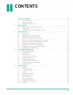
MANUAL ORGANIZATION
Anyone operating or servicing the Sullivan-Palatek air compressor should read this entire manual and be
familiar with its information. The following is a quick guide to the contents in this manual:
SECTION 1: INTRODUCTION
This section contains important basic information regarding the compressor, such as safety precautions and
warranty information.
SECTION 2: SPECIFICATIONS
This section contains all the engineering information related to the specific air compressor, such as
application data and drawings.
SECTION 3: COMPONENT DESCRIPTION
This section contains information about how the different systems and components function within an air
compressor.
SECTION 4: INSTALLATION
This section contains information and guidelines to follow when choosing a site for and installing the air
compressor.
SECTION 5: OPERATION
This section contains an overview of the compressor controls, initial start-up procedures, and how to start
and stop the air compressor.
SECTION 6: MAINTENANCE
This section contains a maintenance schedule and step-by-step instructions for performing common
maintenance procedures.
SECTION 7: TROUbLESHOOTING
This section contains symptoms, causes and remedies for common air compressor malfunctions.
SECTION 8: PARTS LISTING
This section contains procedures for ordering parts, a list of recommended spare parts to keep on hand, and
exploded assembly drawings with corresponding parts lists of all the parts on the air compressor.
I.3
SUPPLEMENTAL DOCUMENTS
For more detailed information on certain components or optional equipment specific to this compressor,
supplemental documents are provided in addition to the standard compressor manual.
Содержание UD Series
Страница 6: ...vi About This Manual ...
Страница 12: ...4 Introduction ...
Страница 24: ...16 Specifications 2 2 DIMENSIONS OPEN AIR COOLED 230V Figure 2 1 GA 30 40 50UD AC VFD 230V R00 ...
Страница 25: ...17 Specifications 2 3 DIMENSIONS OPEN AIR COOLED 460V Figure 2 2 GA 30 40 50UD AC MPC VFD OPEN 460V R00 ...
Страница 26: ...18 Specifications 2 4 DIMENSIONS ENCLOSED AIR COOLED 460V Figure 2 3 GA 40 50 60UDAC ENC S1 R00 ...
Страница 27: ...19 Specifications 2 5 DIMENSIONS ENCLOSED HEAVY DUTY INLET OPTION 460V Figure 2 4 GA 40 50 60UDAC VFD ENC R00 ...
Страница 28: ...20 Specifications 2 6 DIMENSIONS ENCLOSED AIR COOLED HD INLET NO BUSSEL Figure 2 5 GA 60UDAC ENC VFD NB R00 ...
Страница 29: ...21 Specifications 2 7 PIPING AND INSTRUMENTATION AIR COOLED Figure 2 6 P I 15 40D AC MPC VFD R02 ...
Страница 42: ...34 Component Description ...
Страница 52: ...44 Operation ...
Страница 66: ...58 Troubleshooting ...
Страница 74: ...66 Parts Catalog 8 5 COMPRESSOR FRAME AND DRIVE ASSEMBLY Figure 8 1 AS801 25UD 50UD VFD R00 ...
Страница 76: ...68 Parts Catalog 8 6 CONTROL ASSEMBLY OPEN Figure 8 2 1072190415 609 R00 ...
Страница 78: ...70 Parts Catalog 8 7 STARTER ASSEMBLY ENCLOSED Figure 8 3 AS802 405060 PANEL R03 ...
Страница 80: ...72 Parts Catalog 8 8 AIR INLET ASSEMBLY 15 30HP 13 12 11 13 12 4 5 2 3 14 1 Figure 8 4 AS805 030D7H TE R00 ...
Страница 94: ...86 Parts Catalog 8 15 COOLING ASSEMBLY AIR COOLED Figure 8 11 AS804 50UDAC INLINE R00 ...
Страница 100: ...NOTES ...
Страница 101: ...NOTES ...


